ELECTRICAL SYSTEM
M6040, M7040, WSM
9-S31
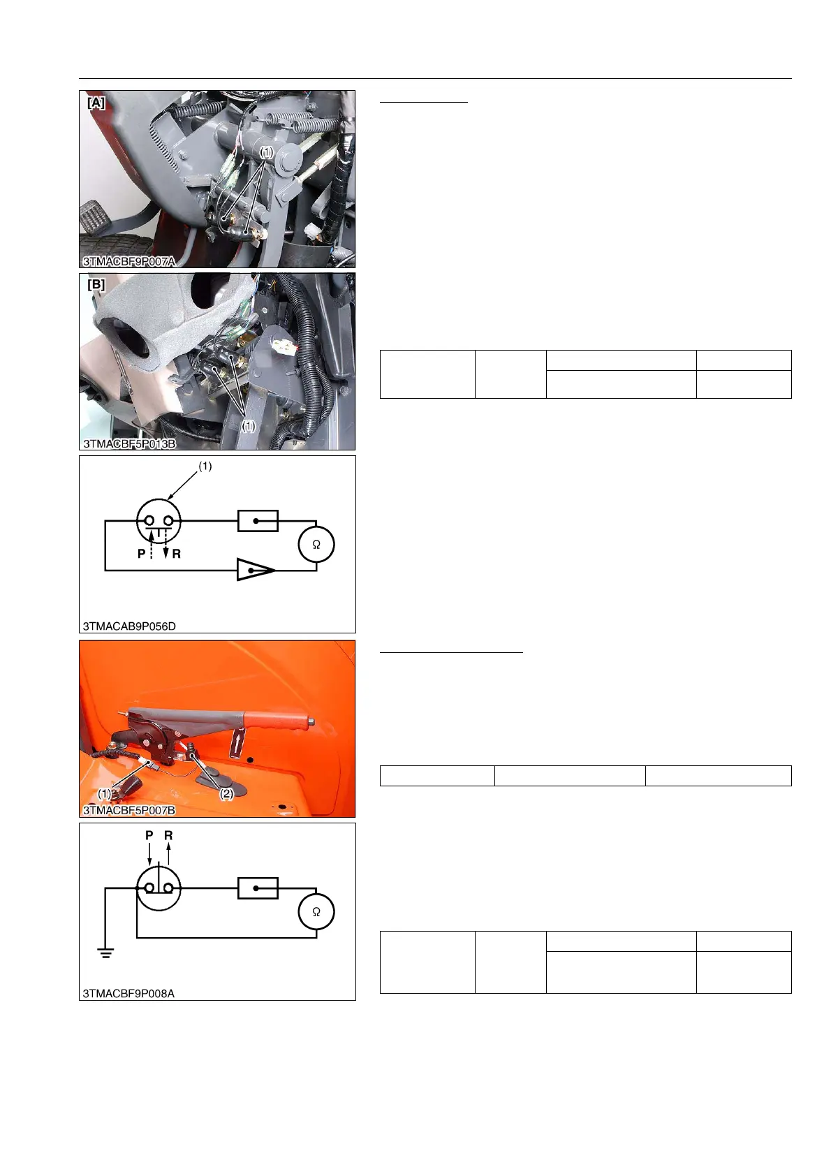
Brake Switch
1) Wiring Harness
1. Disconnect the leads from the brake switch (1).
2. Connect the wiring harness lead terminals to each other and
turn the main switch ON.
3. If the stop lights do not light, the fuse, wiring harness or bulb is
faulty.
2) Brake Switch Continuity
1. Remove the brake switch (1).
2. Check the continuity with an ohmmeter across the switch
terminals.
3. If it does not conduct or any value is indicated when the switch
is released, the switch is faulty.
4. If infinity is not indicated when the switch is pushed, the switch
is faulty.
9Y1210143ELS0048US0
Parking Brake Switch
1) Connector Voltage
1. Remove the connector (1).
2. Turn the main switch ON position.
3. Measure the voltage across the terminal and chassis.
4. If the voltage differs from battery voltage, the wiring harness,
fuse, or main switch is faulty.
2) Parking Brake Switch Continuity
1. Remove the parking brake switch (2).
2. Check the continuity with an ohmmeter across the switch
terminal and chassis.
3. If it does not conduct or any value is indicated when the switch
is released, the switch is faulty.
4. If infinity is not indicated when the switch is pushed, the switch
is faulty.
9Y1210143ELS0049US0
Resistance
(Across switch
terminals)
Reference
value
When switch is pushed Infinity
When switch is released 0 Ω
(1) Brake Switch [A] ROPS Type
[B] CABIN Type
P: Pushed
R: Released
Voltage Terminal – Chassis Approx. battery voltage
Resistance
(Across switch
terminal and
chassis)
Reference
value
When switch is pushed Infinity
When switch is released 0 Ω
(1) Connector
(2) Parking Brake Switch
P: Pushed
R: Released