3.5 Control Circuit Wiring
100 YASKAWA SIEPC71061705H GA700 Series Technical Manual
Table 3.11 Serial Communication Terminals
Type Terminal Terminal Name Function (Signal Level)
Modbus Communication
D+
Communication
input/output (+)
MEMOBUS/Modbus communications
Use an RS-485 cable to connect the drive.
Note:
Set DIP switch S2 to ON to enable the
termination resistor in the last drive in a
MEMOBUS/Modbus network.
• RS-485
• MEMOBUS/Modbus communication protocol
• Maximum 115.2 kbps
D-
Communication
output (-)
AC Shield ground
0 V
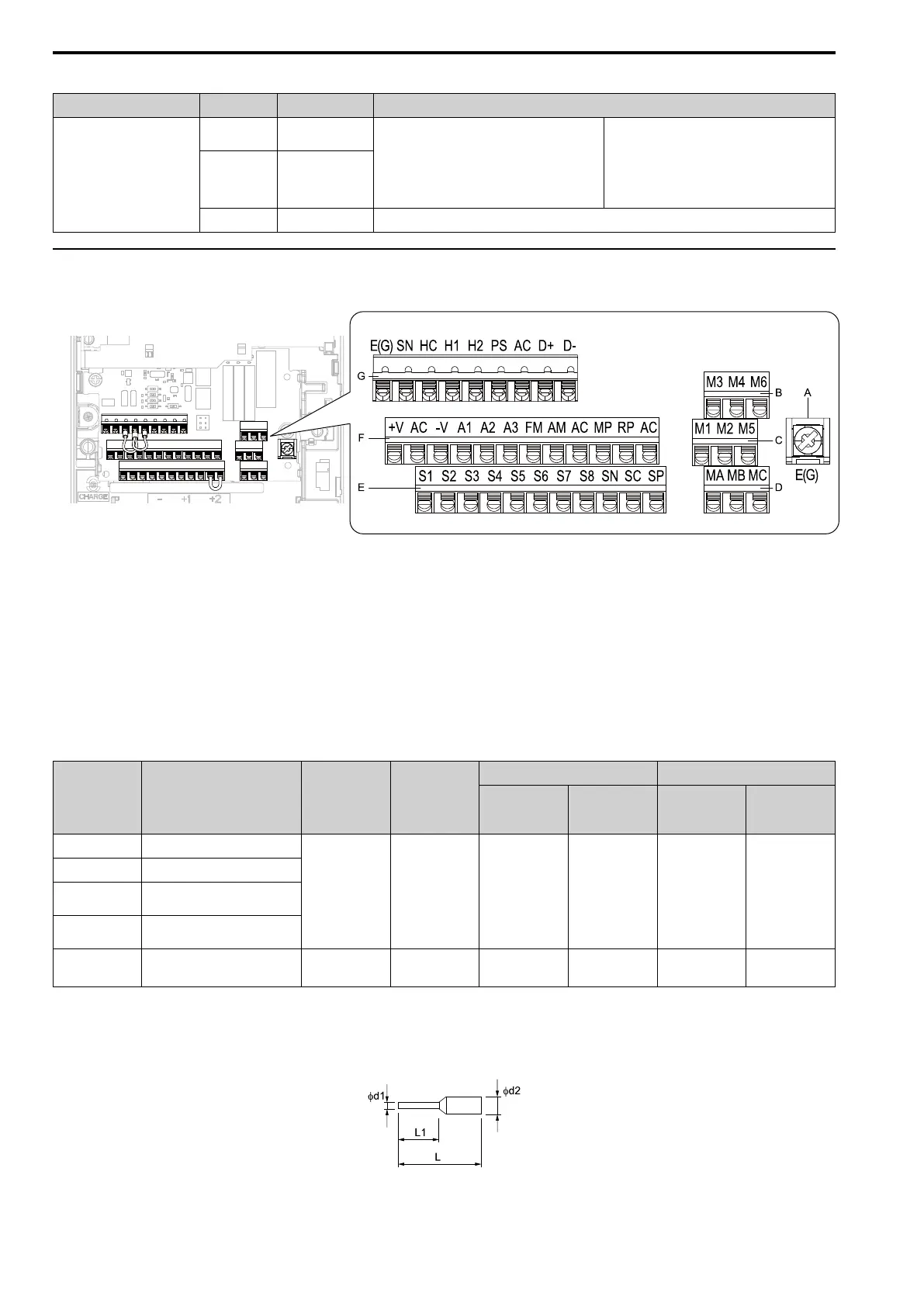
◆ Control Circuit Terminal Configuration
The control circuit terminals are in the positions shown in Figure 3.38.
A - Terminal block (TB5)
B - Terminal block (TB2-3)
C - Terminal block (TB2-2)
D - Terminal block (TB2-1)
E - Terminal block (TB1)
F - Terminal block (TB3)
G - Terminal block (TB4)
Figure 3.38 Control Circuit Terminal Arrangement
■ Control Circuit Wire Gauges and Tightening Torques
Use the tables in this section to select the correct wires. Use shielded wire to wire the control circuit terminal
block. Use crimp ferrules on the wire ends to make the wiring procedure easier and more reliable.
Table 3.12 Control Circuit Wire Gauges and Tightening Torques
Terminal Block Terminal Screw Size
Tightening
Torque
N∙m (lbf∙in)
Bare Wire Crimp Ferrule
Recomm.
Gauge
mm
2
(AWG)
Applicable
Gauge
mm
2
(AWG)
Recomm.
Gauge
mm
2
(AWG)
Applicable
Gauge
mm
2
(AWG)
TB1 S1 - S8, SN, SC, SP
- -
0.75
(18)
• Stranded wire
0.2 - 1.0
(24 - 18)
• Solid wire
0.2 - 1.5
(24 - 16)
0.5
(20)
0.25 - 0.5
(24 - 20)
TB2 M1 - M6, MA, MB, MC
TB3
+V, AC, -V, A1, A2, A3, FM, AM,
AC, MP, RP, AC
TB4
E (G), SN, HC, H1, H2, PS, AC, D
+, D-
TB5 E (G) M3.5
0.5 - 1.0
(4.4 - 8.9)
0.5 - 2
(20 - 14)
1.25
(12)
- -
Crimp Ferrules
Attach an insulated sleeve when you use crimp ferrules. Refer to Table 3.13 for the recommended external
dimensions and model numbers of crimp ferrules.
Use the CRIMPFOX 6, a crimping tool made by PHOENIX CONTACT.
Figure 3.39 External Dimensions of Crimp Ferrules

 Loading...


