3.6 Control I/O Connections
104 YASKAWA SIEPC71061705H GA700 Series Technical Manual
3.6 Control I/O Connections
This section gives information about the settings for the listed control circuit I/O signals.
• MFDI (terminals S1 to S8)
• Pulse train output (terminal MP)
• MFAI (terminals A1 to A3)
• PTC input (terminal A3)
• MFAO (terminals FM, AM)
• MEMOBUS/Modbus communications (terminals D+, D-, AC)
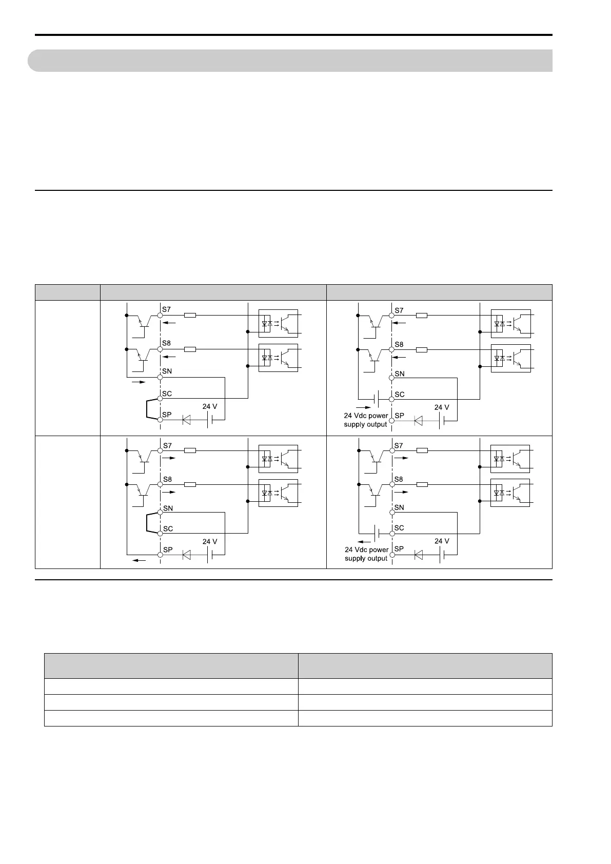
◆ Set Sinking Mode/Sourcing Mode
Close the circuit between terminals SC-SP and SC-SN to set the sinking mode/sourcing mode and the internal/
external power supply for the MFDI terminals. The default setting for the drive is internal power supply sinking
mode.
NOTICE: Damage to Equipment. Do not close the circuit between terminals SP-SN. If you close the circuits between terminals
SC-SP and terminals SC-SN at the same time, it will cause damage to the drive.
Mode Internal Power Supply (Terminal SN-SP) External 24 V power supply
Sinking Mode
(NPN)
Sourcing Mode
(PNP)
◆ Pulse Train Output
You can use pulse train monitor output terminal MP for sourcing mode or for sinking mode.
• Use for sourcing mode
The load impedance changes the voltage level of the pulse train output signal.
Load Impedance
R
L
(kΩ)
Output Voltage
V
MP
(V)
1.5 kΩ or more 5 Vor more
4.0 kΩ or more 8 Vor more
10 kΩ or more 10 V or more
Note:
Use the formula in Figure 3.47 to calculate the necessary load resistance (kΩ) to increase output voltage V
MP
(V).

 Loading...


