Parameter Details
12
12.8 H: Terminal Functions
YASKAWA SIEPC71061705H GA700 Series Technical Manual 803
■ H1-41: Mbus Reg 15C0h bit1 Input Func
No.
(Hex.)
Name Description
Default
(Range)
H1-41
(0B55)
Mbus Reg 15C0h bit1 Input
Func
Sets MFDI function to set to bit 1 of the MEMOBUS register 15C0 (Hex.).
F
(1 - 19F)
■ H1-42: Mbus Reg 15C0h bit2 Input Func
No.
(Hex.)
Name Description
Default
(Range)
H1-42
(0B56)
Mbus Reg 15C0h bit2 Input
Func
Sets MFDI function to set to bit 2 of the MEMOBUS register 15C0 (Hex.).
F
(1 - 19F)
◆ Multi-Function Digital Input Setting Values
Selects a function set with H1-01 to H1-08.
■ 0: 3-Wire Sequence
Setting Value Function Description
0 3-Wire Sequence
Sets the direction of motor rotation for 3-wire sequence.
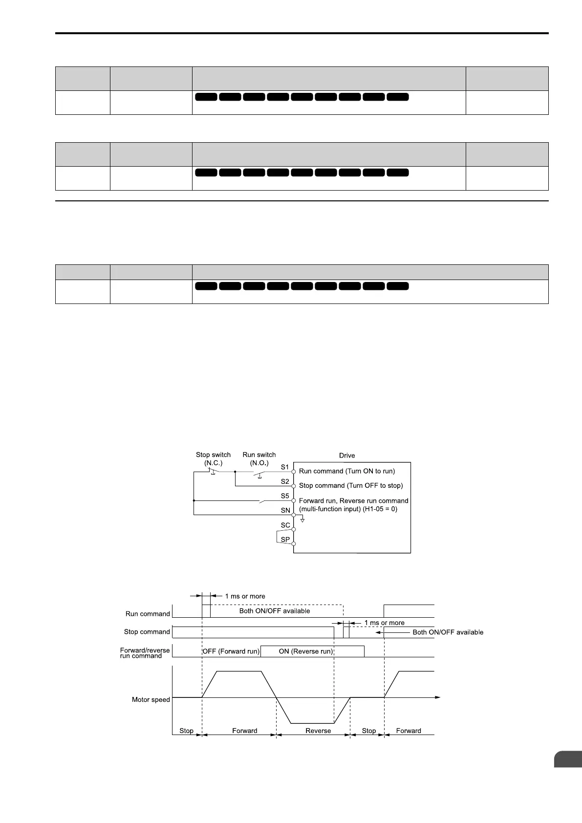
If the 3-wire sequence is set to a terminal that is not MFDI terminals S1 and S2, these terminals will be the input
terminals for Forward run/Reverse run command. The drive will automatically set terminal S1 to Run command
(RUN) and terminal S2 to Stop command (STOP).
When terminal S1 (Run command) activates for 1 ms minimum, the drive rotates the motor. When terminal S2
(Stop command) deactivates, the drive stops. When terminal Sx that is set in 3-wire sequence deactivates, the
drive operates in the forward direction, and when it activates, the drive operates in the reverse direction.
WARNING! Sudden Movement Hazard. Set the MFDI parameters before you close control circuit switches. Incorrect Run/Stop
circuit sequence settings can cause serious injury or death from moving equipment.
WARNING! Sudden Movement Hazard. When you use a 3-Wire sequence, set A1-03 = 3330 [Initialize Parameters = 3-Wire
Initialization] and make sure that b1-17 = 0 [Run Command at Power Up = Disregard Existing RUN Command] (default). If you
do not correctly set the drive parameters for 3-Wire operation before you energize the drive, the motor can suddenly rotate
when you energize the drive.
Figure 12.80 3-Wire Sequence Wiring Example
.
Figure 12.81 3-Wire Sequence Time Chart

 Loading...


