6.3 MEMOBUS/Modbus Communications
280 YASKAWA SIEPC71061705H GA700 Series Technical Manual
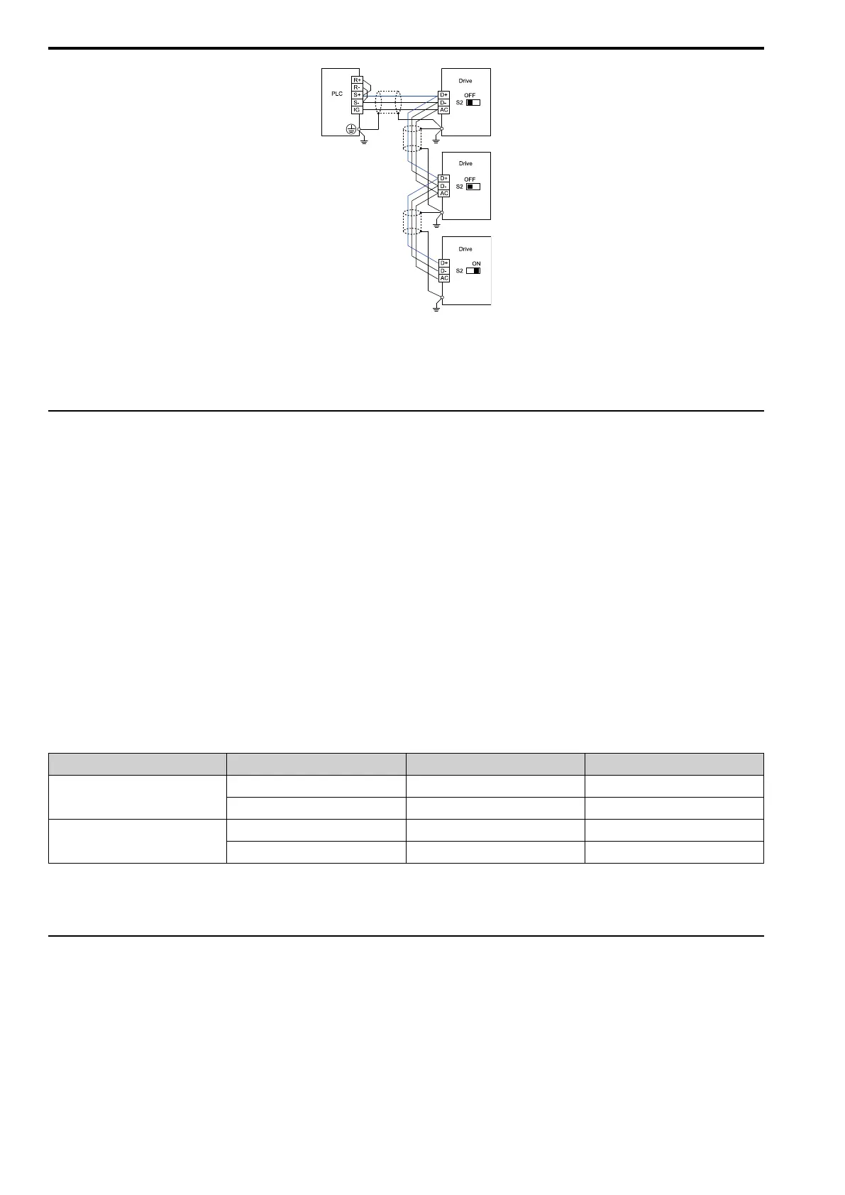
Figure 6.4 Wiring Diagram for More than One Drive
Note:
Set DIP switch S2 to the ON position on the last drive of the MEMOBUS/Modbus communication network to enable the termination
resistor.
◆ MEMOBUS/Modbus Drive Operations
Drive parameters will apply to the settings when the drive is running during MEMOBUS/Modbus
communications. This section gives information about the available functions and their related parameters.
■ Executable Functions
A PLC can do these operations with MEMOBUS/Modbus communications. Parameter settings (except H5-xx) do
not have an effect on the availability of these operations.
• Monitor the drive status and operate the drive
• Set and view parameters
• Fault Reset
• Multi-function input setting (The input command from MEMOBUS/Modbus communications and MFDI
terminals (S1 to S8) are linked by a logical OR operation.)
■ Drive Control
Select the external command that sets the frequency references and motor run/stop with MEMOBUS/Modbus
communications. Use the information in Table 6.3 to set the parameters as specified by the application.
Table 6.3 Necessary Parameter Settings for Drive Control from MEMOBUS/Modbus
LOCAL Control Selected No. Name Setting Value
External reference 1
b1-01 Frequency Reference Selection 1 2 [Memobus/Modbus Communications]
b1-02 Run Command Selection 1 2 [Memobus/Modbus Communications]
External reference 2
b1-15 Frequency Reference Selection 2 2 [Memobus/Modbus Communications]
b1-16 Run Command Selection 2 2 [Memobus/Modbus Communications]
For more information about operation mode selection, refer to [Frequency Reference Selection 1] and b1-02 [Run
Command Selection 1]. Refer to H1-xx = 2 [MFDI Function Select = External Reference 1/2 Selection] for more
information about external commands.
◆ Communications Timing
To prevent overrun of the slave side, the master cannot send a message to the same drive for a selected length of
time.
To prevent overrun of the master side, the slave cannot send a response message to the master for a selected length
of time.
This section gives information about message timing.

 Loading...


