Parameter Details
12
12.6 E: Motor Parameters
YASKAWA SIEPC71061705H GA700 Series Technical Manual 749
■ E2-09: Motor Mechanical Loss
No.
(Hex.)
Name Description
Default
(Range)
E2-09
(0316)
Expert
Motor Mechanical Loss
Sets the mechanical loss of the motor. It is set as a percentage of E2-11 [Motor Rated Power].
Usually it is not necessary to change this setting.
0.0%
(0.0 - 10.0%)
Adjust this parameter in these conditions. The drive adds the configured mechanical loss to the torque reference
value as a torque compensation value:
• There is a large quantity of torque loss from motor bearing friction.
• There is a large quantity of torque loss in fans and pumps.
■ E2-10: Motor Iron Loss
No.
(Hex.)
Name Description
Default
(Range)
E2-10
(0317)
Motor Iron Loss
Sets the motor iron loss.
Determined by o2-04, C6-
01
(0 - 65535 W)
■ E2-11: Motor Rated Power
No.
(Hex.)
Name Description
Default
(Range)
E2-11
(0318)
Motor Rated Power
Sets the motor rated output in the units from o1-58 [Motor Power Unit Selection].
Determined by o2-04, C6-
01
(0.00 - 650.00)
The drive automatically sets this parameter to the value input for “Motor Rated Power” during Auto-Tuning.
◆ E3: V/f Pattern for Motor 2
E3 parameters [V/f Pattern for Motor 2] set the control mode and V/f pattern used for motor 2.
Note:
V/f preset patterns equivalent to those set with E1-03 [V/f Pattern Selection] are not available for E3 parameters. Use E3-04 [Motor 2
Maximum Output Frequency] to E3-10 [Motor 2 Minimum Output Voltage] to manually set the V/f pattern.
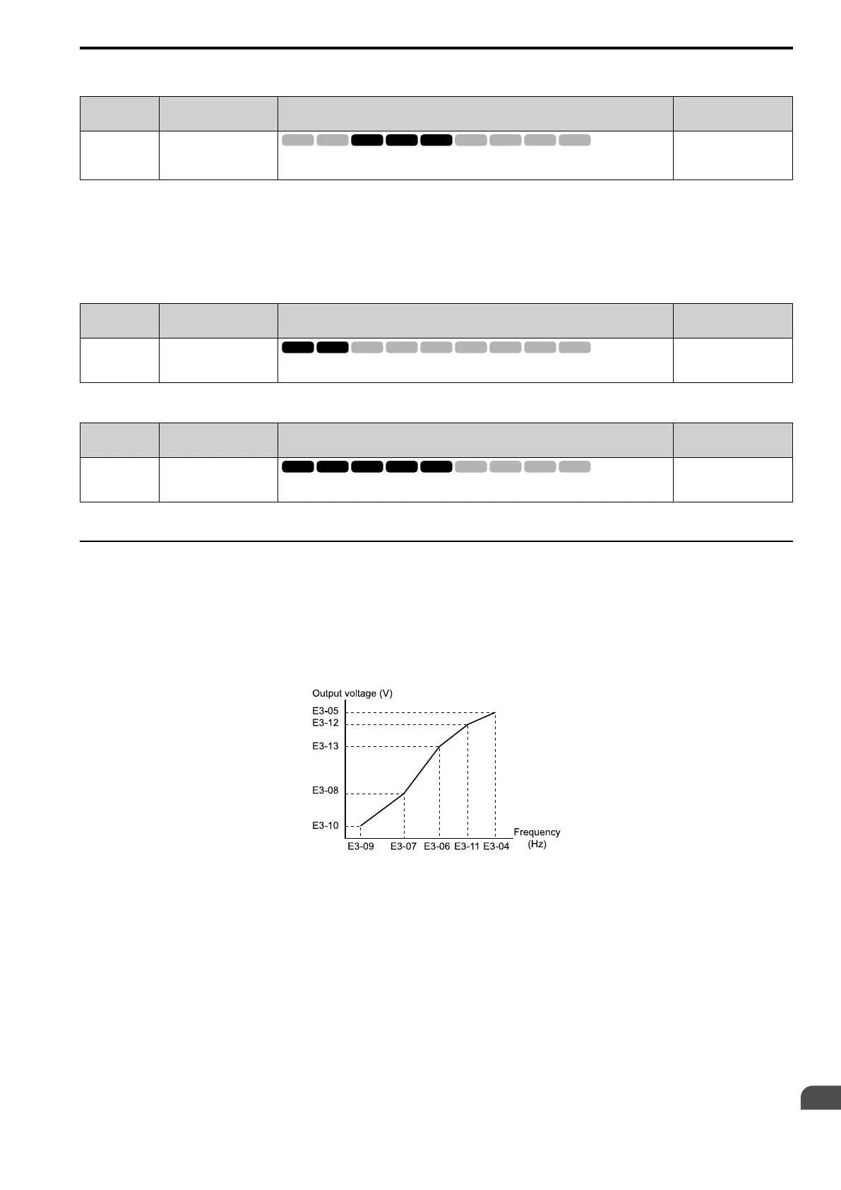
■ Notes on Manually Setting V/f Patterns
Figure 12.76 Motor 2 V/f Pattern Diagram
• To configure a linear V/f pattern at frequencies lower than E3-06 [Motor 2 Base Frequency], set E3-07 = E3-09
[Motor 2 Mid Point A Frequency = Motor 2 Minimum Output Frequency]. In this application, the drive ignores
E1-08 [Mid Point A Voltage].
• Set the five frequencies as specified by these rules:
E3-09 ≤ E3-07 < E3-06 ≤ E3-11 ≤ E3-04 [Motor 2 Minimum Output Frequency ≤ Motor 2 Mid Point A
Frequency < Motor 2 Base Frequency ≤ Motor 2 Mid Point B Frequency ≤ Motor 2 Maximum Output
Frequency]
Incorrect settings will trigger oPE10 [V/f Data Setting Error].
• If E3-11 = 0.0 Hz, the drive will ignore the V/f pattern settings.
• When you use A1-03 [Initialize Parameters] to initialize the drive, the drive will reset the manually set values
for E3-04 to E3-13 [Motor 2 Base Voltage] to default values.

 Loading...


