Parameter List
11
11.12 n: Special Adjustment
YASKAWA SIEPC71061705H GA700 Series Technical Manual 559
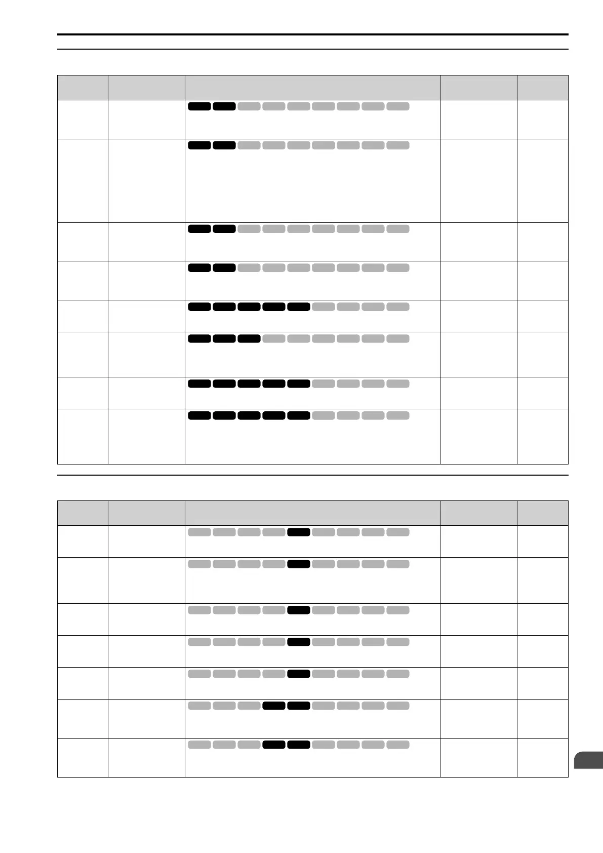
◆ n3: High Slip/Overexcite Braking
No.
(Hex.)
Name Description
Default
(Range)
Ref.
n3-01
(0588)
Expert
HSB Deceleration
Frequency Width
Sets the amount by which the output frequency is to be lowered during high-slip
braking, as a percentage of E1-04 [Maximum Output Frequency], which represents the
100% value.
5%
(1 - 20%)
922
n3-02
(0589)
Expert
HSB Current Limit
Level
Sets the maximum current output during high-slip braking as a percentage, where E2-01
[Motor Rated Current (FLA)] is 100%. Also set the current suppression to prevent
exceeding drive overload tolerance.
Note:
The upper limit to the setting range changes when the setting for C6-01 [Normal /
Heavy Duty Selection] changes.
• 150% when C6-01 = 0 [Heavy Duty Rating]
• 110% when C6-01 = 1 [Normal Duty Rating]
Determined by C6-01
and L8-38
(0 - 150%)
923
n3-03
(058A)
Expert
HSB Dwell Time at Stop
Sets the dwell time, a length of time when high-slip braking is ending and during which
the motor speed decreases and runs at a stable speed. For a set length of time, the drive
will hold the actual output frequency at the minimum output frequency set in E1-09.
1.0 s
(0.0 - 10.0 s)
923
n3-04
(058B)
Expert
HSB Overload Time
Sets the time used to detect oL7 [High Slip Braking Overload], which occurs when the
output frequency does not change during high-slip braking. Usually it is not necessary
to change this parameter.
40 s
(30 - 1200 s)
923
n3-13
(0531)
OverexcitationBraking
(OEB) Gain
Sets the gain value that the drive multiplies by the V/f pattern output value during
overexcitation deceleration to calculate the overexcitation level.
1.10
(1.00 - 1.40)
923
n3-14
(0532)
Expert
OEB High Frequency
Injection
Sets the function that injects harmonic signals during overexcitation deceleration.
0 : Disabled
1 : Enabled
0
(0, 1)
924
n3-21
(0579)
HSB Current
Suppression Level
Sets the upper limit of the current that is suppressed at the time of overexcitation
deceleration as a percentage of the drive rated current.
100%
(0 - 150%)
924
n3-23
(057B)
Overexcitation Braking
Operation
Sets the direction of motor rotation where the drive will enable overexcitation.
0 : Disabled
1 : Enabled Only when Rotating FWD
2 : Enabled Only when Rotating REV
0
(0 - 2)
924
◆ n4: Adv Open Loop Vector Tune
No.
(Hex.)
Name Description
Default
(Range)
Ref.
n4-60
(1B80)
Motoring Low Speed
Comp Gain
Sets a compensation gain to improve the control qualities for motoring loads in the low
speed range.
100.0%
(50.0 - 200.0%)
925
n4-61
(1B81)
Low Speed Comp
Frequency Level
Sets a frequency at which the settings n4-60 [Motoring Low Speed Comp Gain] and n4-
62 [Regen Low Speed Comp Gain] are enabled. When the output frequency < n4-61, the
drive adjusts the torque to agree with the settings for n4-60 and n4-62. Usually it is not
necessary to change this setting.
6.00 Hz
(0.50 - 12.00 Hz)
925
n4-62
(1B82)
Regen Low Speed Comp
Gain
Sets a compensation gain to improve the control qualities for regenerative loads in the
low speed range.
100.0 %
(50.0 - 500.0%)
925
n4-63
(1B83)
Speed
EstimateResponse@
High Freq
Sets the responsiveness of the speed estimation in high speed ranges, where the output
frequency is ≥ n4-67 [Estimate Gain Switchover Freq].
60.0
(0.1 - 300.0)
925
n4-64
(1B84)
Speed Estimate
Response@Low Freq
Sets the responsiveness of the speed estimation in low speed ranges, where 0 ≤ the
output frequency, which is < n4-67 [Estimate Gain Switchover Freq].
60.0
(0.1 - 300.0)
925
n4-65
(1B85)
Flux Estimate
Response@High Freq
Sets the responsiveness of the magnetic flux estimation in high speed ranges, where the
output frequency is ≥ n4-67 [Estimate Gain Switchover Freq]. Usually it is not
necessary to change this setting.
1.00
(0.50 - 3.00)
926
n4-66
(1B86)
Flux Estimate Response
@Low Freq
Sets the responsiveness of the magnetic flux estimation in low speed ranges, where 0 ≤
the output frequency, which is < n4-67 [Estimate Gain Switchover Freq]. Usually it is
not necessary to change this setting.
1.50
(0.50 - 3.00)
926

 Loading...


