12.8 H: Terminal Functions
846 YASKAWA SIEPC71061705H GA700 Series Technical Manual
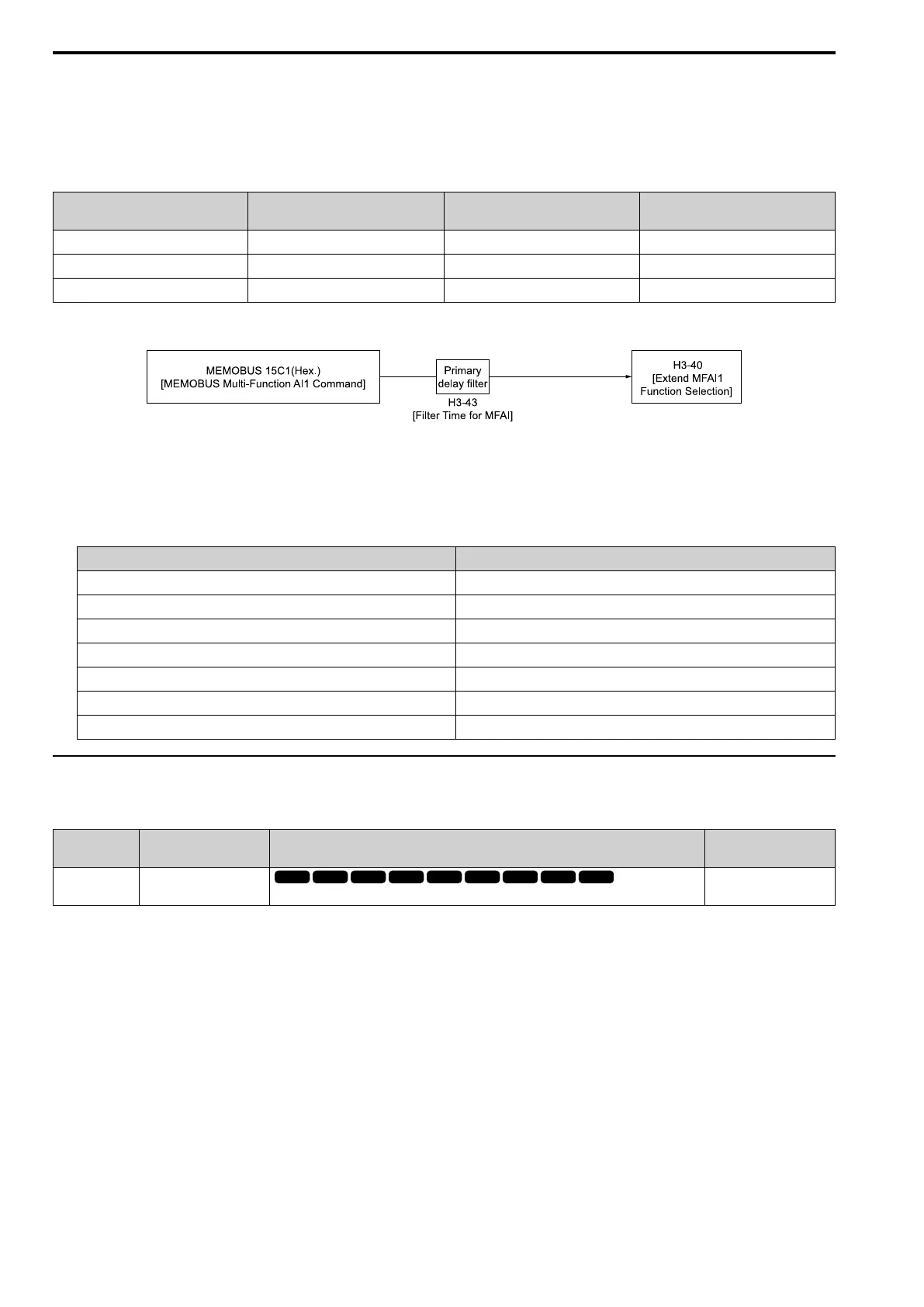
■ MEMOBUS/Modbus Multi-Function AI1 to 3 Function Selection
Let the MFAI function be assigned to MEMOBUS/Modbus register 15C1 to 15C3 (Hex.) [Mbus Reg 15C1h
through 15C3h Input Function]. Use H3-40 to H3-42 [Mbus Reg 15C1h through 15C3h Input Function] to set the
function and use H3-43 [Mbus Reg Inputs FilterTime Const] to set the input filter.
Table 12.70 MEMOBUS Multi-Function AI Command Register
Register No.
(Hex.)
Name Range
*1
Parameter
15C1 Mbus Reg 15C1h Input Function -32767 to 32767 H3-40
15C2 Mbus Reg 15C2h Input Function -32767 to 32767 H3-41
15C3 Mbus Reg 15C3h Input Function -32767 to 32767 H3-42
*1 Set as 100% = 4096.
Figure 12.106 Functional Block Diagram for MEMOBUS Multi-Function AI Command 1
Note:
• Refer to H3-xx “MFAI Setting Values” for the analog input setting values.
• When you will not use the terminal, set H3-40 to H3-42 = F. The through mode function is not supported.
• You cannot use H3-40 to H3-42 to set these MFAI terminals:
H3-xx Setting Value Function
0 Frequency Reference
1 Frequency Gain
2 Auxiliary Frequency Reference 1
3 Auxiliary Frequency Reference 2
30 DWEZ Analog Input 1
31 DWEZ Analog Input 2
32 DWEZ Analog Input 3
◆ H3: MFAI Parameters
■ H3-01: Terminal A1 Signal Level Select
No.
(Hex.)
Name Description
Default
(Range)
H3-01
(0410)
Terminal A1 Signal Level
Select
Sets the input signal level for MFAI terminal A1.
0
(0 - 3)
0 : 0-10V (Lower Limit at 0)
The voltage signal is 0 Vdc to 10 Vdc. The minimum input level limit is 0%. The drive will read a negative input
signal caused by gain and bias settings as 0%.
1 : -10 to +10V (Bipolar Reference)
The voltage signal is -10 Vdc to 10 Vdc. Signals of both positive and negative polarities are enabled. When the
drive uses this setting as the frequency reference, a Forward Run command will run the motor in reverse and a
Reverse Run command will run the motor forward. The gain and bias settings will cause the signal to be a
negative number.
2 : 4 to 20 mA
The current signal is 4 mA to 20 mA. The minimum input level limit is 0%. The minimum input level is limited to
0%, so that a negative input signal due to gain and bias settings will be read as 0%.
3 : 0 to 20 mA
The current signal is 0 mA to 20 mA. The minimum input level limit is 0%. The minimum input level is limited to
0%, so that a negative input signal due to gain and bias settings will be read as 0%.

 Loading...


