Parameter List
11
11.17 U: Monitors
YASKAWA SIEPC71061705H GA700 Series Technical Manual 587
◆ U6: Operation Status Monitors
No.
(Hex.)
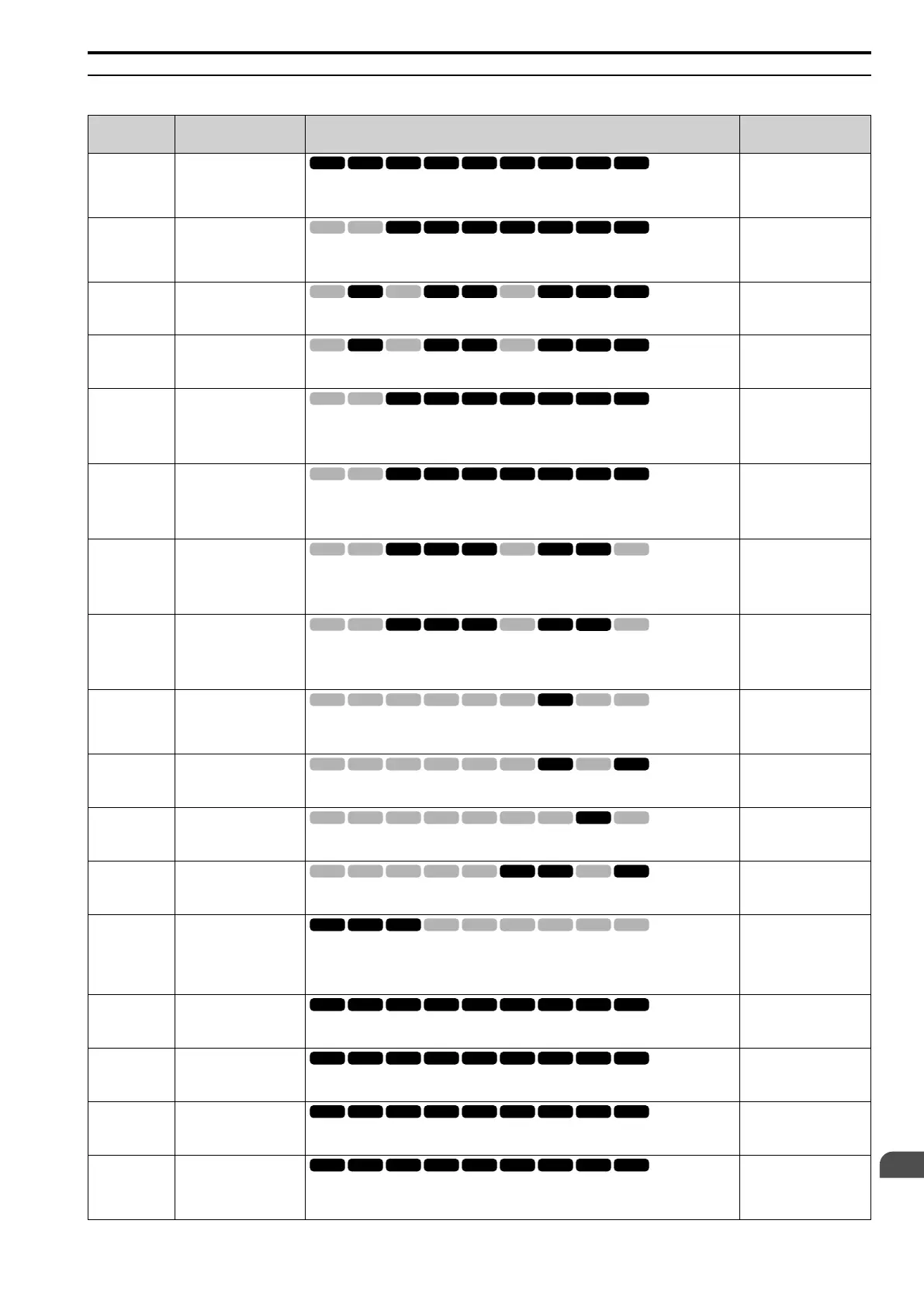
Name Description MFAO Signal Level
U6-01
(0051)
Iq Secondary Current
Shows the value calculated for the motor secondary current (q-Axis) as a percentage of the motor
rated secondary current.
Unit: 0.1%
10 V: Motor secondary
rated current (0 V to +10 V)
U6-02
(0052)
Id ExcitationCurrent
Shows the value calculated for the motor excitation current (d-Axis) as a percentage of the motor
rated secondary current.
Unit: 0.1%
10 V: Motor secondary
rated current (0 V to +10 V)
U6-03
(0054)
ASR Input
Shows the ASR input value as a percentage of the maximum frequency.
Unit: 0.01%
10 V: Maximum frequency
(0 V to +10 V)
U6-04
(0055)
ASR Output
Shows the ASR output value as a percentage of the motor rated secondary current.
Unit: 0.01%
10 V: Motor secondary
rated current (0 V to +10 V)
U6-05
(0059)
OutputVoltageRef: Vq
Shows the drive internal voltage reference for motor secondary current control (q-Axis).
Unit: 0.1 V
200 V Class: 10 V = 200
Vrms
400 V Class: 10 V = 400
Vrms
(0 V to +10 V)
U6-06
(005A)
OutputVoltageRef: Vd
Shows the drive internal voltage reference for motor excitation current control (d-Axis).
Unit: 0.1 V
200 V Class: 10 V = 200
Vrms
400 V Class: 10 V = 400
Vrms
(0 V to +10 V)
U6-07
(005F)
Expert
q-Axis ACR Output
Shows the output value for current control related to motor secondary current (q axis).
Unit: 0.1 %
200 V Class: 10 V = 200
Vrms
400 V Class: 10 V = 400
Vrms
(0 V to +10 V)
U6-08
(0060)
Expert
d-Axis ACR Output
Shows the output value for current control related to motor excitation current (d axis).
Unit: 0.1 %
200 V Class: 10 V = 200
Vrms
400 V Class: 10 V = 400
Vrms
(0 V to +10 V)
U6-09
(07C0)
Expert
AdvPhase Compen Δθcmp
Displays the data on forward phase compensation for the calculation results of the amount of
control axis deviation.
Unit: 1 °
5 V: 180 ° (-10 V to +10 V)
U6-10
(07C1)
Expert
ContAxisDeviation Δθ
Shows the deviation between the γδ-Axis that the drive uses for motor control and the dq-Axis.
Unit: 0.1 °
5 V: 180 ° (-10 V to +10 V)
U6-13
(07CA)
Expert
MagPolePosition(Enc)
Shows the value of the flux position detection.
Unit: 0.1 °
10 V: 180° (-10 V to +10 V)
U6-14
(07CB)
Expert
MagPolePosition(Obs)
Shows the value of the flux position estimation.
Unit: 0.1 °
10 V: 180 ° (-10 V to +10
V)
U6-17
(07D1)
Expert
Energy Save Coeff
Shows the total time of direction of motor rotation detections for Speed Estimation Speed
Searches. This value adjusts b3-26 [Direction Determination Level].
Note:
Upper limit is +32767 and lower limit is -32767.
No signal output available
U6-18
(07CD)
Enc 1 Pulse Counter
Shows the number of pulses for speed detection (PG1).
Unit: 1 pulse
10 V: 65536
U6-19
(07E5)
Enc 2 Pulse Counter
Shows the number of pulses for speed detection (PG2).
Unit: 1 pulse
10 V: 65536
U6-20
(07D4)
UP/DOWN 2 Bias Value
Shows the bias value used to adjust the frequency reference.
Unit: 0.1%
10 V: Maximum Frequency
U6-21
(07D5)
Offset Frequency
Shows the total value of d7-01 to d7-03 [Offset Frequency 1 to 3] selected with Add Offset
Frequency 1 to 3 [H1-xx = 44 to 46].
Unit: 0.1%
10 V: Maximum Frequency

 Loading...


