6.3 MEMOBUS/Modbus Communications
288 YASKAWA SIEPC71061705H GA700 Series Technical Manual
Note:
• You can write the EEPROM to the drive a maximum of 100,000 times. Do not frequently execute the Enter command (0900 (Hex.))
that is written to EEPROM.
• The Enter command register is write-only. If this register is read, it will cause a Register Number Error (02 (Hex.)).
• When the command data or broadcast message is transmitted to the drive, the Enter command is not necessary.
■ Functions of the Enter Command when Replacing a Previous Generation Drive
When you replace a previous generation Yaskawa drive with this product, you must set the Enter command
function for this product the same as the previous product. The Enter command function is different for Yaskawa
G7, F7-series, and V7-series drives.
Use H5-11 to set the Enter command function:
• When replacing G7 and F7 series drives, set H5-11 = 0 [ENTER Command Required].
• When replacing V7 series drives, set H5-11 = 1 [ENTER Command Not Required].
• When replacing 1000-series drives, set H5-11 to the same value as the drive you replaced.
Table 6.14 Enter Command Function Differences
H5-11 Settings H5-11 = 0 H5-11 = 1
The drive you replaced G7, F7 V7
Time when the parameter settings are enabled
When the drive receives the Enter command from the
master
When you change the parameter settings
Upper and lower limit check
Checks the upper and lower limits and considers the
related parameter settings.
Checks the upper and lower limit of the changed
parameter only.
Default setting of related parameters
Will not change related parameter settings. You must
change the parameters manually.
Automatically changes the default settings for the related
parameters.
Fault detection when you set more than one parameter
Accepts and responds as usual to correct setting data if the
data contains parameter setting errors. The drive discards
the disabled setting data, but will not return an error
message.
If there is a setting error in a parameter, the drive
responds with a fault. The drive discards the data that was
sent.
◆ Self-Diagnostics
The drive can use Self-Diagnositcs to find the operation of the serial communications interface circuit. Self-
Diagnostics connects the transmission terminal to the reception terminal on the control circuit. It then transmits
the data sent by the drive and makes sure that the drive can communicate correctly.
Use this procedure to do Self-Diagnostics:
1. Energize the drive.
2. Set H1-06 = 67 [Terminal S6 Function Select = Communications test mode].
3. De-energize the drive.
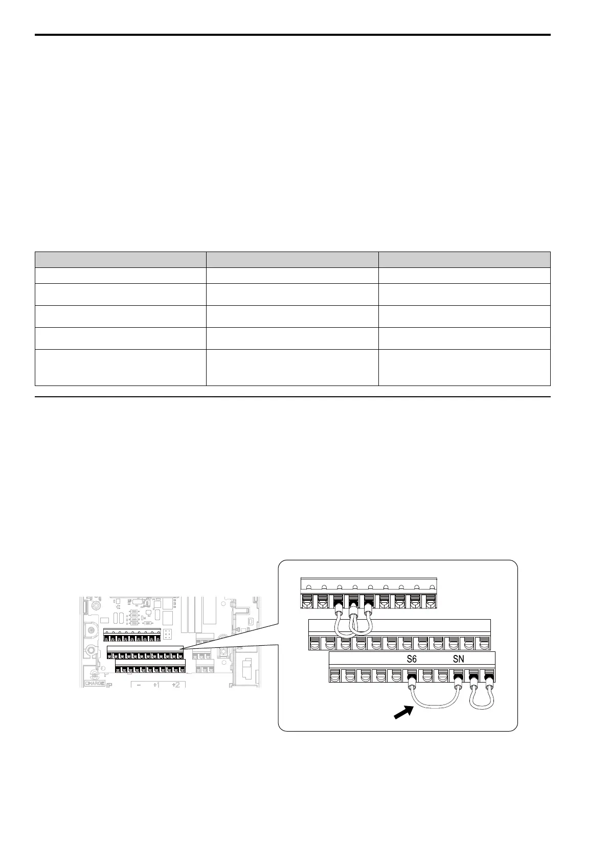
4. Connect a jumper between control circuit terminals S6 and SN.
Make sure terminal SC and terminal SP are connected by a wire jumper.
Figure 6.8 Self-Diagnostics Jumper Terminals
5. Energize the drive.
6. When normal, the keypad will show PASS [MEMOBUS/Modbus Communications Test Mode Normal].
When there is an error, the keypad will show CE [MEMOBUS/Modbus Communications Error].

 Loading...


