10.6 Drive Derating
440 YASKAWA SIEPC71061705H GA700 Series Technical Manual
10.6 Drive Derating
You must derate the drive capacity to operate the drive above the rated temperature, altitude, and default carrier
frequency.
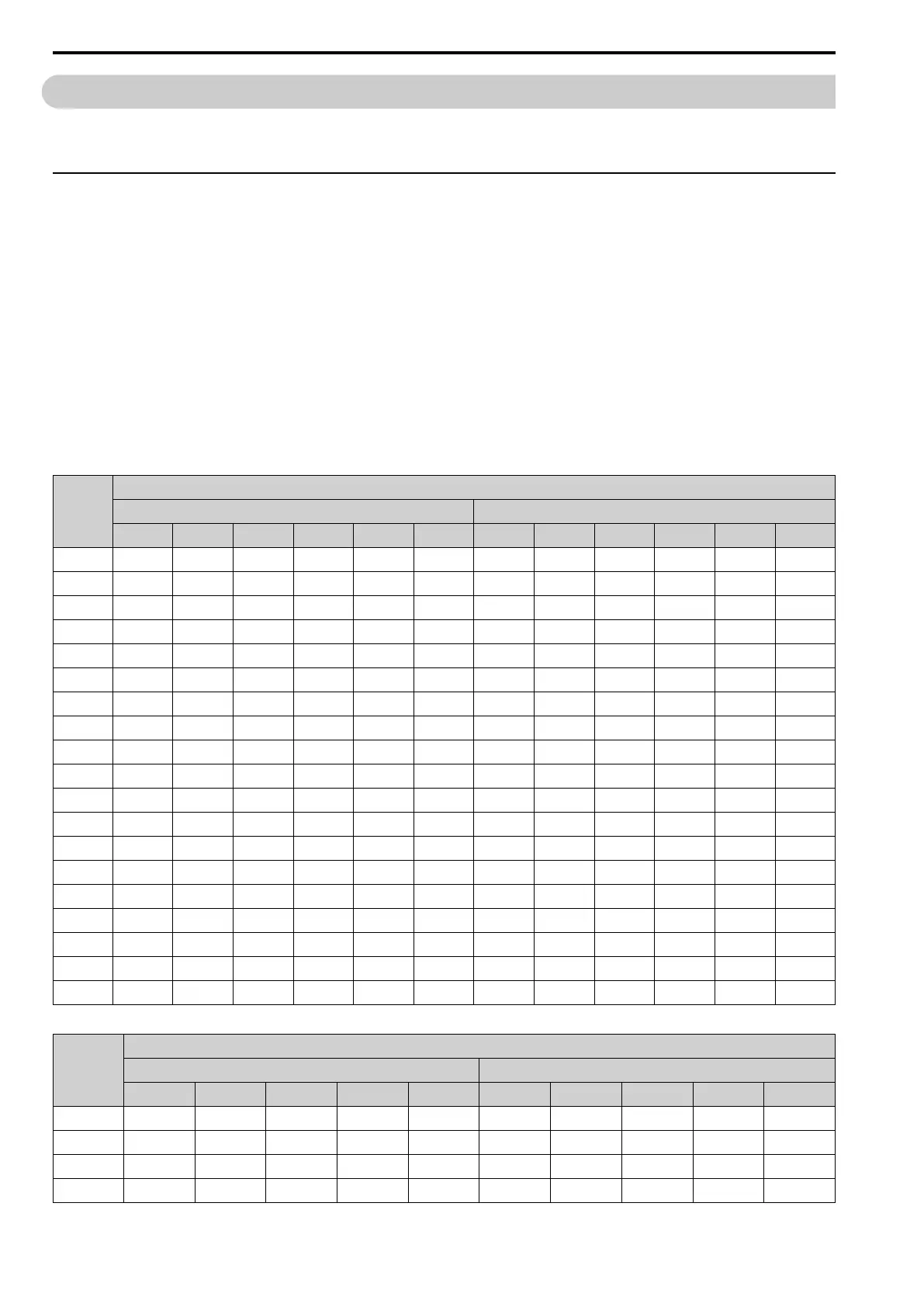
◆ Carrier Frequency Settings and Rated Current Values
Table 10.13 and Table 10.16 show how the drive rated output current changes when the C6-02 [Carrier
Frequency Selection] value changes.
The output current value changes linearly as the carrier frequency changes. You can use the values from the tables
to calculate a frequency that is not shown. When A1-02 = 4 [Control Method Selection = AOLV], refer to Table
10.14 and Table 10.17.
When A1-02 = 6 [AOLV/ PM], refer to Table 10.15 and Table 10.18.
Note:
The drive only applies the carrier frequency derating of the output current to the reference output current value of oL2 [Drive Overload].
The drive will not derate the 100% output rated current of parameters and monitors as specified in the output rated current shown in
Model-Specific Specifications (200 V Class) on page 428 and Model-Specific Specifications (400 V Class) on page 431.
■ 200 V Class
Table 10.13 Carrier Frequency and Rated Current Derating When A1-02 = 0, 1, 2, 3, 5, 7, 8
Model
Rated Current (A)
Heavy Duty Rating (HD1) Normal Duty Rating (ND1)
2 kHz 5 kHz 8 kHz 10 kHz 12.5 kHz 15 kHz 2 kHz 5 kHz 8 kHz 10 kHz 12.5 kHz 15 kHz
2004
3.2 3.2 3.2 3.1 2.9 2.78 3.5 3.3 2.9 2.7 2.4 2.1
2006
5.0 5.0 5.0 4.8 4.6 4.3 6 5.6 5 4.6 4.1 3.6
2010
8.0 8.0 8.0 7.4 6.6 5.8 9.6 9.0 8 7.4 6.6 5.8
2012
11.0 11.0 11.0 10.4 9.6 8.8 12 11.7 11 10.5 9.9 9.3
2018
14.0 14.0 14.0 12.6 10.8 9.1 17.5 16.1 14 12.6 10.8 9.1
2021
17.5 17.5 17.5 16.1 14.3 12.6 21 19.6 17 16.1 14.3 12.5
2030
25.0 25.0 25.0 23.0 20.5 18.0 30 28.0 25 23.0 20.5 18.0
2042
33.0 33.0 33.0 29.3 24.8 20.2 42 38.4 33 29.4 24.9 20.4
2056
47.0 47.0 47.0 43.4 38.9 34.4 56 52.4 47 43.4 38.9 34.4
2070
60.0 60.0 60.0 56.0 51.0 46 70 66.0 60 56.0 51.0 46.0
2082
75.0 75.0 75.0 68.6 60.5 53 82 82.0 75 68.8 61.0 53.1
2110
88.0 88.0 88.0 80.5 71.0 62 110 102.7 92 84.3 75.2 66.0
2138
115.0 115.0 115.0 105.1 92.8 81 138 128.8 115 105.8 94.3 82.8
2169
145.0 145.0 125.2 112.0 - - 169 152.7 128.3 112.0 - -
2211
180.0 180.0 155.2 138.6 - - 211 190.2 158.9 138.1 - -
2257
215.0 215.0 184.8 164.7 - - 257 230.4 190.5 163.9 - -
2313
283.0 283.0 249.0 226.4 - - 313 288.5 251.7 227.1 - -
2360
346.0 346.0 294.3 259.8 - - 360 330.8 287.6 258.8 - -
2415
415.0 415.0 365.2 332.0 - - 415 391.3 355.7 332.0 - -
Table 10.14 Carrier Frequency and Rated Current Derating When A1-02 = 4 [AOLV]
Model
Rated Current (A)
Heavy Duty Rating (HD1) Normal Duty Rating (ND1)
2 kHz 5 kHz 8 kHz 10 kHz 12.5 kHz 2 kHz 5 kHz 8 kHz 10 kHz 12.5 kHz
2004
3.2 3.2 3.0 2.8 2.6 3.5 3.0 2.4 2.1 1.7
2006
5.0 5.0 4.6 4.3 4.0 6 5.1 4 3.6 2.8
2010
8.0 8.0 6.7 5.8 4.5 9.6 8.2 7 5.8 4.6
2012
11.0 11.0 9.8 8.8 7.7 12 11.1 10 9.3 8.4

 Loading...


