3.4 Main Circuit Terminal Block Wiring Procedure
88 YASKAWA SIEPC71061705H GA700 Series Technical Manual
3.4 Main Circuit Terminal Block Wiring Procedure
DANGER! Electrical Shock Hazard. Do not examine, connect, or disconnect wiring on an energized drive. Before servicing,
disconnect all power to the equipment and wait for the time specified on the warning label at a minimum. The internal capacitor
stays charged after the drive is de-energized. The charge indicator LED extinguishes when the DC bus voltage decreases
below 50 Vdc. When all indicators are OFF, remove the covers before measuring for dangerous voltages to make sure that the
drive is safe. If you do work on the drive when it is energized, it will cause serious injury or death from electrical shock.
The procedures to wire the main circuit terminal block are different for different drive models. Refer to Table 3.4
for procedures by drive model.
Table 3.4 Types of Wiring Procedure for the Main Circuit Terminal Block
Model Procedure Ref.
2004 - 2211
4002 - 4168
Procedure A 88
2257 - 2415
4208 - 4675
Procedure B 91
◆ Wire the Main Circuit Terminal Block with Procedure A
■ Notes on Wiring the Main Circuit Terminal Block
Read these notes before you wire the main circuit terminal block.
• Use UL-Listed, vinyl-coated insulated copper wires for operation with a continuous maximum permitted
temperature of 75 °C at 600 V.
• Remove all unwanted objects that are near the terminal block connections.
• Remove the insulation from the connection wires to the wire stripping lengths shown in the manual.
• Do not use bent or crushed wires. Remove the damaged end of the wire before you use it. Incorrect connections
can cause death or serious injury from fire.
• Do not solder stranded wire. Soldered wire connections can become loose over time and cause unsatisfactory
drive performance.
• If you use stranded wire, make sure that all of the wire strands are in the connection. Also, do not twist the
stranded wire too much. Incorrect connections can cause death or serious injury from fire.
• Put the wire all the way into the terminal block. Remove the insulation from the wire to the recommended wire
stripping length to fit the wire with insulation in the plastic housing.
• Use a torque driver, torque ratchet, or torque wrench for the screws. A slotted driver or a hex tool will be
necessary to wire the screw clamp terminal. Use applicable tools as specified by the recommended conditions in
the product manual.
• If you use power tools to tighten the terminal screws, use a low speed setting (300 to 400 r/min). Failure to obey
can cause damage to the terminal screws.
• Wire gauges on existing drive models to be replaced may not match wire gauge ranges on new drives. Refer to
the drive manuals for correct wire sizes.
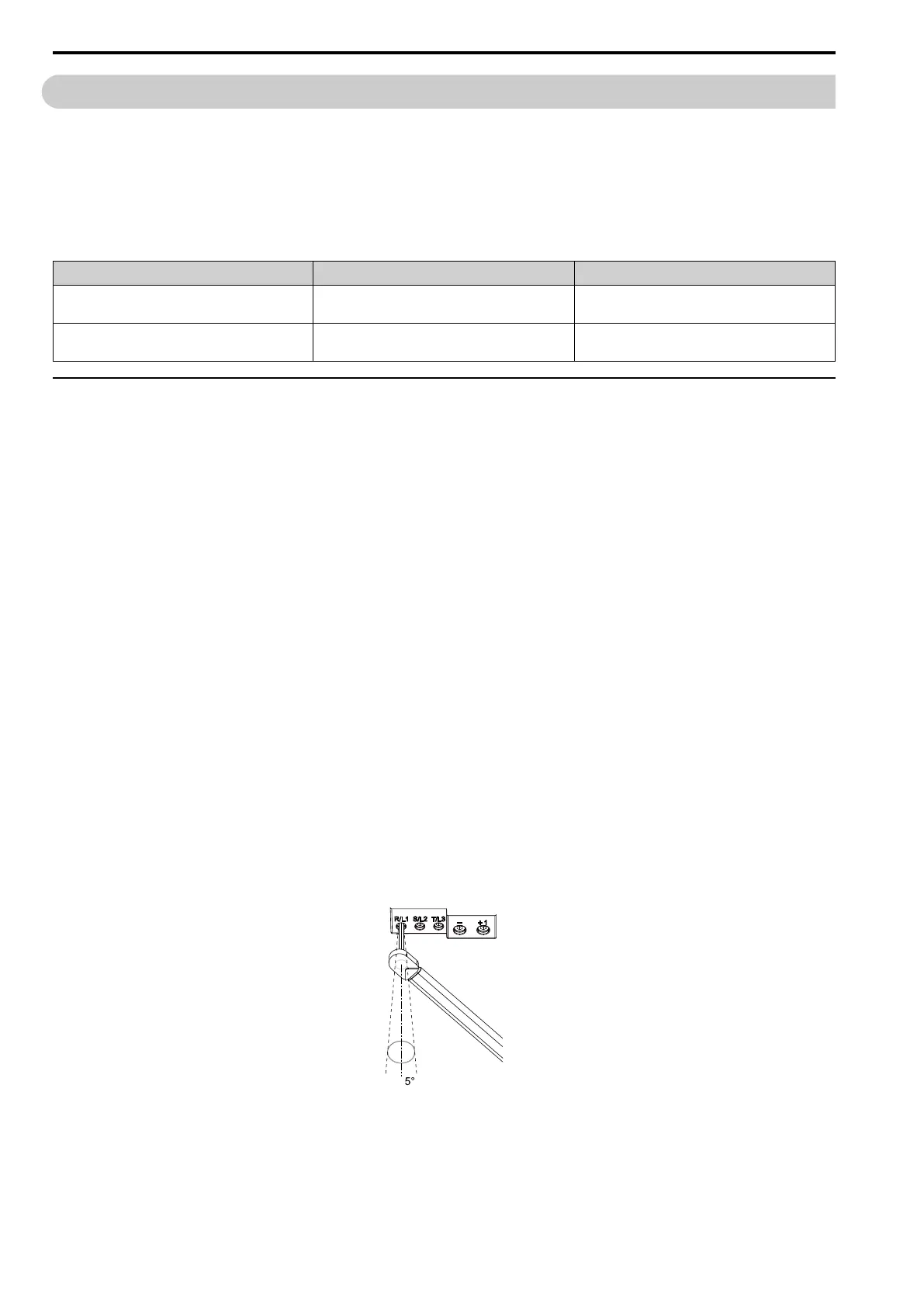
• Do not tighten the terminal screws at an angle of 5 degrees or more. Failure to obey can cause damage to the
terminal screws.
• If you damage a terminal screw, contact Yaskawa or your nearest sales representative.
Figure 3.21 Permitted Angle
• Put the bit all the way into the hex socket to tighten the hex socket cap screw.
• When you tighten slotted screws, hold the straight-edge screwdriver perpendicularly to the screw. Make sure
that you align the end of the straight-edge screwdriver with the screw groove.

 Loading...


