Electrical Installation
3
3.6 Control I/O Connections
YASKAWA SIEPC71061705H GA700 Series Technical Manual 105
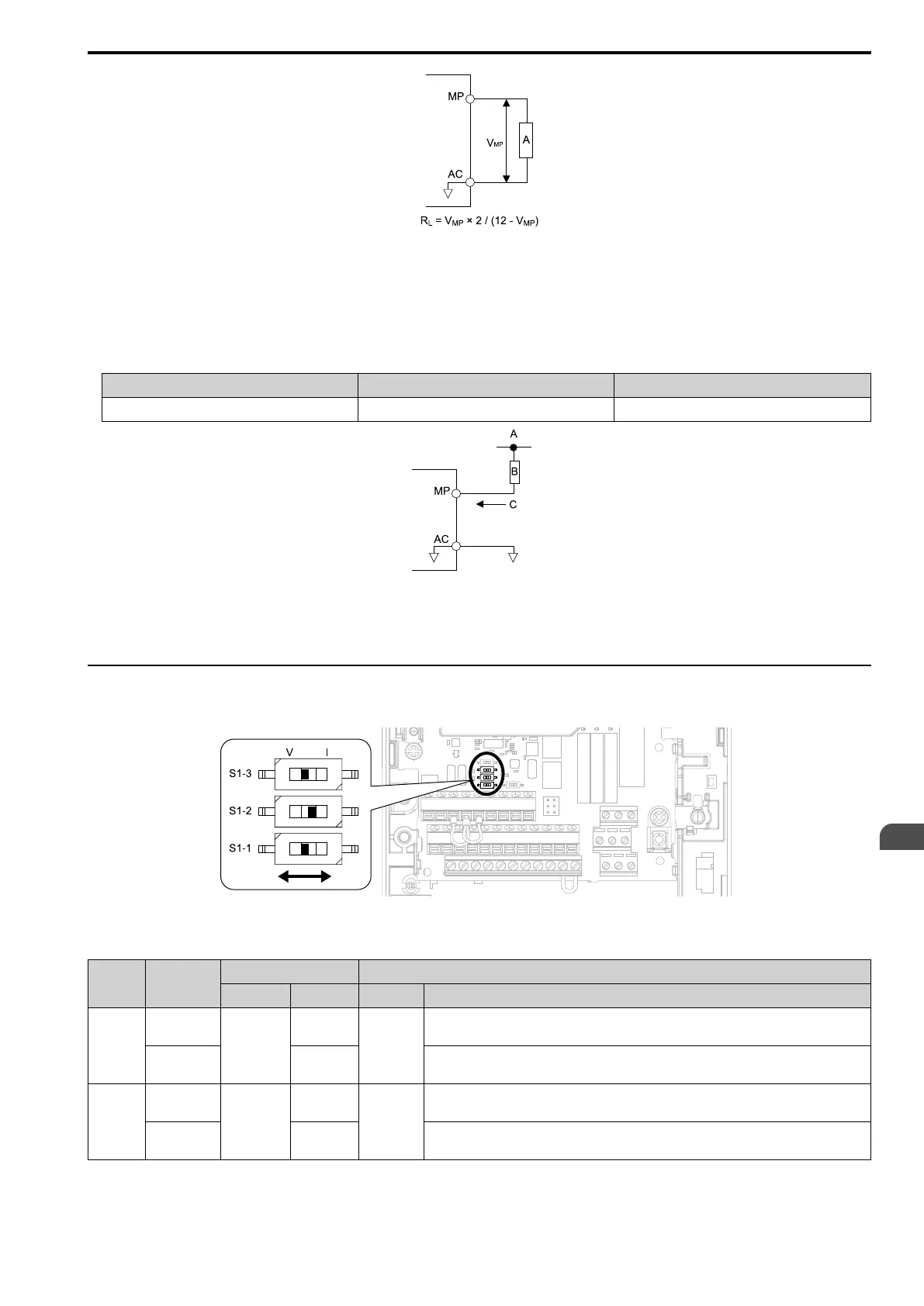
A - Load Impedance
Figure 3.47 Wiring to Use Pulse Train Output in Sourcing Mode
• Use in sinking mode
The external power supply changes the voltage level of the pulse train output signal. Keep the voltage from an
external source between 10.8 Vdc to 16.5 Vdc. Adjust the load impedance to keep the current at 16 mA or
lower.
External Power Supply (V) Load Impedance (kΩ) Sinking current (mA)
10.8 Vdc to 16.5 Vdc 1.0 kΩ or more 16 mA maximum
A - External power supply
B - Load Impedance
C - Sinking current
Figure 3.48 Wiring to Use Pulse Train Output in Sinking Mode
◆ Set Input Signals for MFAI Terminals A1 to A3
Use terminals A1 to A3 to input a voltage or a current signal. Set the signal type as shown in Table 3.15.
Figure 3.49 Location of DIP Switch S1
Table 3.15 MFAI Terminals A1 to A3 Signal Settings
Terminal Input Signal
DIP Switch Settings Parameter
Switch Setting No. Signal Level
A1
Voltage input
S1-1
V
(Default)
H3-01
0: 0 V to 10 V/0% to 100% (input impedance: 20 kΩ)
1: -10 V to +10 V/-100% to 100% (input impedance: 20 kΩ)
Current input I
2: 4 mA to 20 mA/0% to 100% (input impedance: 250 Ω)
3: 0 mA to 20 mA/0% to 100% (input impedance: 250 Ω)
A2
Voltage input
S1-2
V
H3-09
0: 0 V to 10 V/0% to 100% (input impedance: 20 kΩ)
1: -10 V to +10 V/-100% to 100% (input impedance: 20 kΩ)
Current input
I
(Default)
2: 4 mA to 20 mA/0% to 100% (input impedance: 250 Ω)
3: 0 mA to 20 mA/0% to 100% (input impedance: 250 Ω)

 Loading...


