Parameter Details
12
12.8 H: Terminal Functions
YASKAWA SIEPC71061705H GA700 Series Technical Manual 867
• When you input a pulse train frequency that is less than the value of H6-08, the pulse train input is 0.0 Hz.
• Set H6-01 = 0, 1, or 2 [Terminal RP Pulse Train Function = Frequency Reference, PID Feedback Value, or
PID Setpoint Value] to enable this parameter.
• When H6-01 = 3 [Speed Feedback (V/F Control)], the drive applies the setting of F1-14 [Encoder Open-Circuit
Detect Time] to the minimum frequency.
■ H6-09: Voltage Phase Sync MP Selection
No.
(Hex.)
Name Description
Default
(Range)
H6-09
(156E)
Voltage Phase Sync MP
Selection
Set whether to output the pulse synchronized with drive output voltage phase from the pulse train
monitor output terminal MP. This parameter is only enabled when H6-06 = 102 [Terminal MP
Monitor Selection = Output Frequency] and H6-07 = 0 [Terminal MP Frequency Scaling = 0
Hz].
0
(0, 1)
0 : Disabled
1 : Enabled
◆ H7: Virtual MFIO Selection
The virtual I/O function performs the following.
• Inputs the result of the output from the MFDO terminal to the MFDI terminal without external wiring.
• Inputs the result of the output from the MFAO terminal to the MFAI terminal without external wiring.
This can simplify the external wiring and reduce the cost.
WARNING! Sudden Movement Hazard. Before you do a test run, make sure that the setting values for virtual input and output
function parameters are correct. Virtual input and output functions can have different default settings and operation than wired
input and output functions. Incorrect function settings can cause serious injury or death.
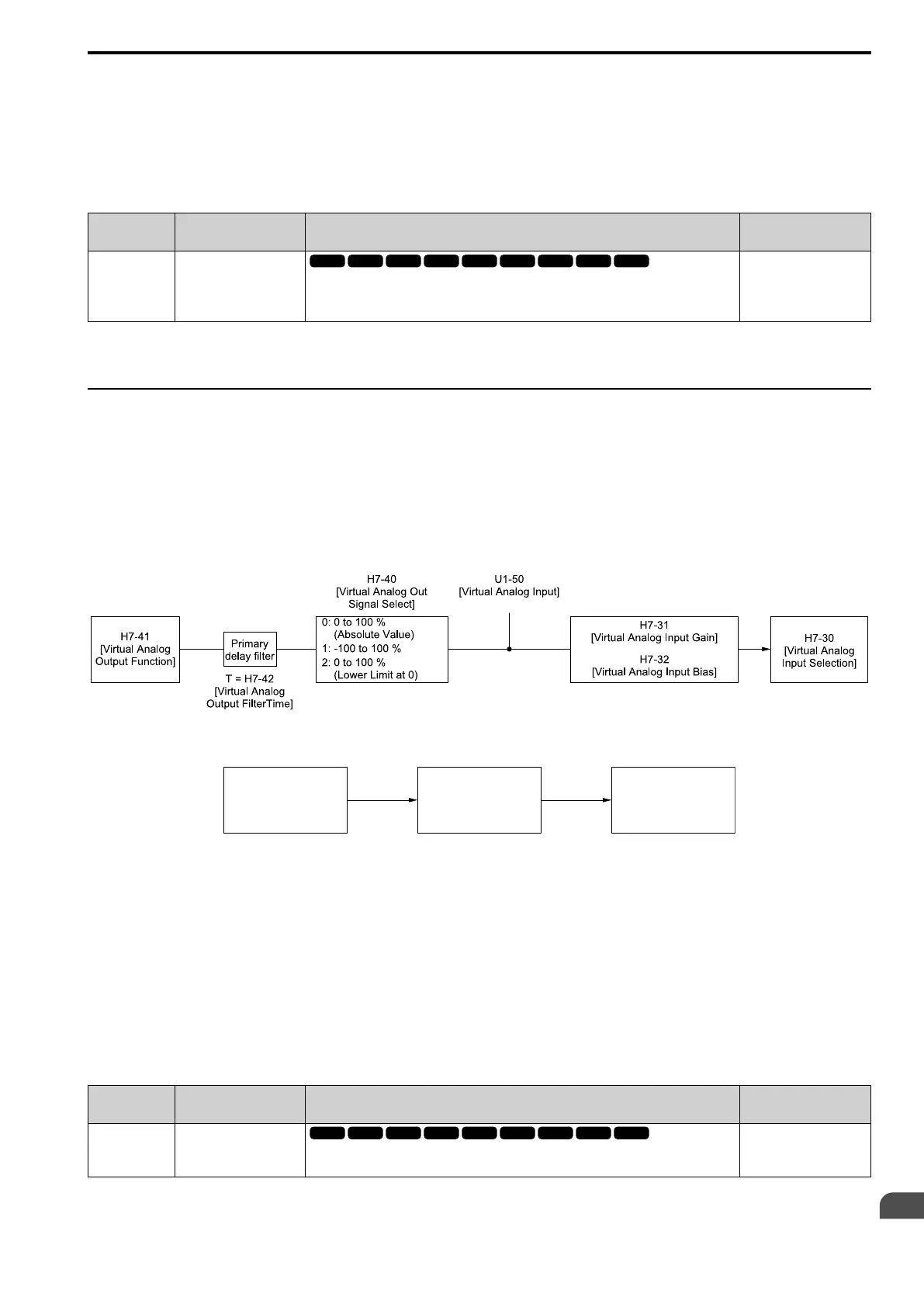
Figure 12.120 Virtual Analog I/O Functional Block Diagram
Figure 12.121 Virtual Digital I/O Functional Block Diagram
Note:
• Refer to H1-xx Multi-Function Digital Input Setting Values on page 803 for more information on the virtual digital input setting values.
• Refer to H2-xx MFDO Setting Values on page 830 for more information on the virtual digital output setting values.
• Refer to H3-xx Multi-Function Analog Input Terminal Settings on page 851 for more information on the virtual analog input setting
values.
• Refer to H4-xx H4: Analog Outputs on page 856 for more information on the virtual analog output setting values.
• You cannot set 0 [3-Wire Sequence] and 20 or 2F [External Fault] to H7-01 to H7-04 [Virtual Multi-Function Input 1 to 4].
• When you will not use the terminal, set H7-01 to H7-04 = F. The through mode function is not supported.
• You cannot use the virtual I/O function selection and the multi-function input for DI-A3 at the same time.
■ H7-00: Virtual MFIO selection
No.
(Hex.)
Name Description
Default
(Range)
H7-00
(116F)
Expert
Virtual MFIO selection
Sets the function to enable and disable the virtual I/O function. Set this parameter to 1 to operate
the virtual I/O function.
0
(0, 1)
0 : Disabled
H7-01
[Virtual Multi-Function
Input 1]
H7-11
[Virtual Output
1 Delay Time]
H7-10
[Virtual Multi-Function
Output 1]

 Loading...


