Electrical Installation
3
3.5 Control Circuit Wiring
YASKAWA SIEPC71061705H GA700 Series Technical Manual 103
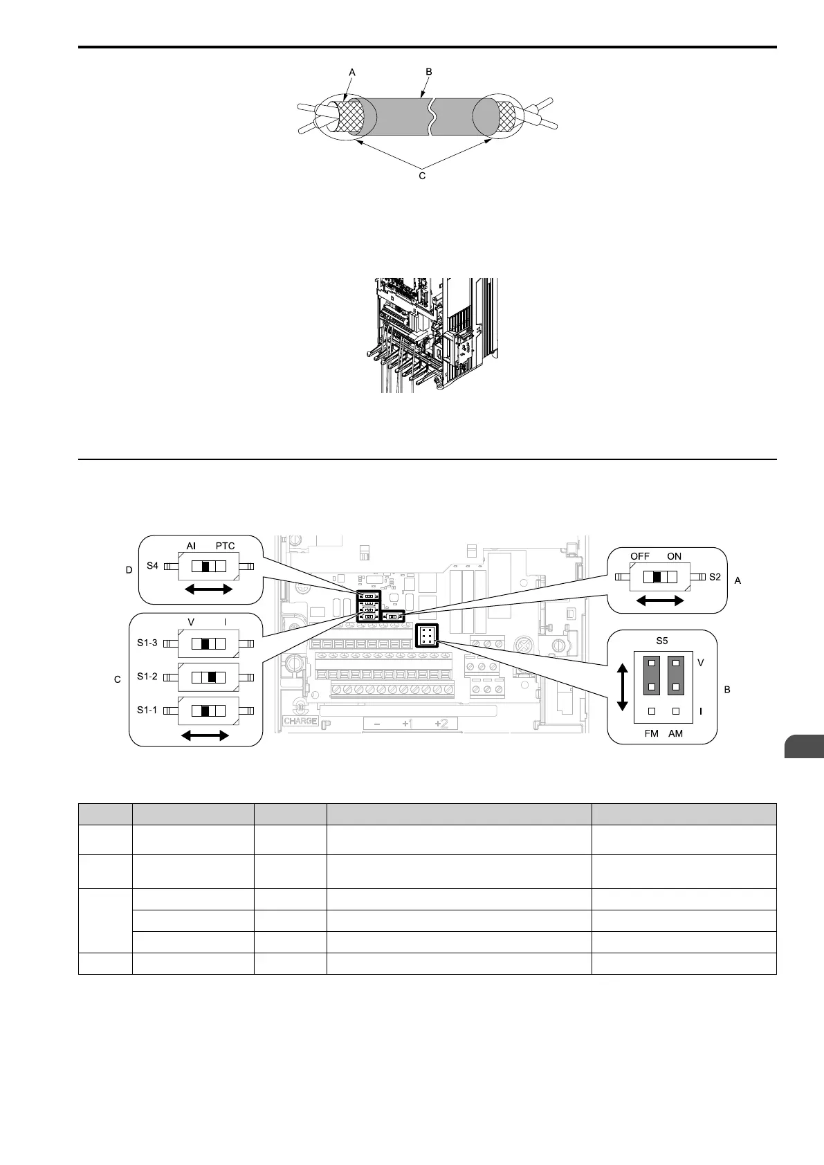
A - Connect the shield to terminal E (G) of the drive.
B - Sheath
C - Insulate with electrical tape or shrink tubing.
Figure 3.44 Prepare the Ends of Shielded Wire
3. Put the cable through the clearance in the wiring cover.
Figure 3.45 Control Circuit Wiring
4. Install the LED status ring board, front cover, and the keypad to their initial positions.
◆ Switches and Jumpers on the Terminal Board
The terminal board has switches to adapt the drive I/Os to the external control signals as shown in Figure 3.46.
Set the switches to select the functions for each terminal.
Figure 3.46 Locations of Switches
Table 3.14 I/O Terminals and Switches Functions
Position Switch Terminal Function Default
A DIP switch S2 -
Enables and disables the MEMOBUS/Modbus communications
termination resistor.
OFF
B Jumper Switch S5 FM, AM Sets terminals FM and AM to voltage or current output.
FM: V (voltage output)
AM: V (voltage output)
C
DIP switch S1-1 A1 Sets the input signal type (voltage/current). V (voltage input)
DIP switch S1-2 A2 Sets the input signal type (voltage/current). I (current input)
DIP switch S1-3 A3 Sets the input signal type (voltage/current). V (voltage input)
D DIP switch S4 A3 Sets MFAI or PTC input. AI (analog input)

 Loading...


