Electrical Installation
3
3.9 Braking Resistor Installation
YASKAWA SIEPC71061705H GA700 Series Technical Manual 111
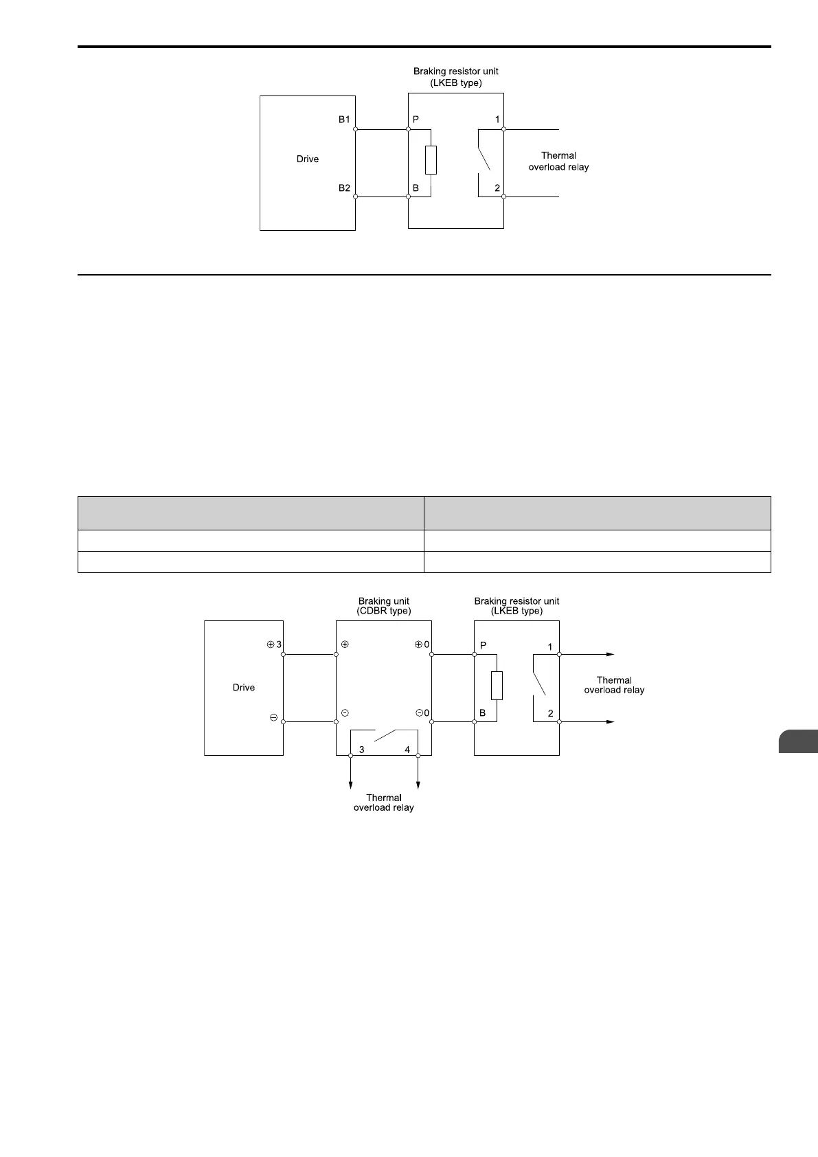
Figure 3.57 Install a Braking Resistor Unit: LKEB-Type
◆ Install a Braking Unit Connection: CDBR-Type
To install a CDBR-type braking unit, connect terminal +3 on the drive to terminal + on the braking unit, and
connect terminal - on the drive to terminal - on the braking unit. Terminal +2 on the drive is not necessary for
CDBR-type braking unit connections.
Set L8-55 = 0 [Internal DB TransistorProtection = Disable].
Note:
• To install a CDBR-type braking unit to the drive models 2004 to 2138 and 4002 to 4168 that have a built-in braking transistor, connect
drive terminal B1 to terminal + on the braking unit.
• A junction terminal is necessary to connect a braking unit (CDBR-series) to drive models 2169, 2211, 4140, or 4168. To wire the
braking unit, install a junction terminal that can connect to wires in the range specified for the drive, peripheral devices, and options.
This table shows recommended junction terminals. Contact Yaskawa or your nearest sales representative for more information about
selection and installation of the junction terminal.
Drive Model
Junction Terminal Model
Manufacturer: Mibu Denki Industrial Co., Ltd.
2169, 4140, 4168 DTK-200N × 2P
*1
2211 DTK-300N × 2P
*1
*1 The junction terminal must have two or more poles.
Figure 3.58 Install a Braking Unit: CDBR-Type/Braking Resistor Unit: LKEB-Type
■ Braking Unit Connection Wire Gauge (CDBR-Type)
To comply with IP20 when you connect the braking unit (CDBR-type) to drive models 2257 to 2415 or 4208 to
4675, refer to Table 3.17 and Table 3.18 to select the wires.

 Loading...


