7.6 Parameter Setting Errors
360 YASKAWA SIEPC71061705H GA700 Series Technical Manual
7.6 Parameter Setting Errors
Parameter setting errors occur when multiple parameter settings do not agree, or when parameter setting values
are not correct. Refer to the table in this section, examine the parameter setting that caused the error, and remove
the cause of the error. You must first correct the parameter setting errors before you can operate the drive. The
drive will not send notification signals for the faults and alarms when these parameter setting errors occur.
Code Name Causes Possible Solutions
oPE01 Drive Capacity Setting Error
The value set in o2-04 [Drive Model (KVA)
Selection] does not agree with the drive model.
Set o2-04 to the correct value.
Code Name Causes Possible Solutions
oPE02 Parameter Range Setting Error
Parameter settings are not in the applicable setting
range.
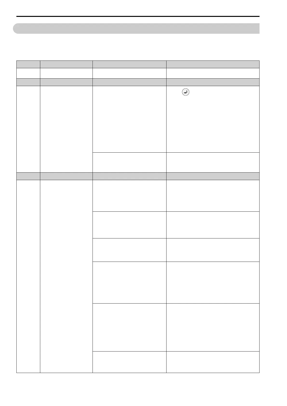
1. Push to show U1-18 [oPE Fault Parameter], and find
parameters that are not in the applicable setting range.
2. Correct the parameter settings.
Note:
• If more than one error occurs at the same time, other oPExx
errors have priority over oPE02.
• If you copy the parameter settings from a drive with
software versions PRG: 01021 or earlier, and restore the
parameter settings to a drive with PRG: 01022 or later, the
drive can detect oPE02. If U1-18 [oPE Fault Parameter]
shows n8-36 [HFI Frequency Level for L Tuning], set n8-36
to the default setting and do High Frequency Injection
Tuning.
The “PRG” column on the nameplate on the right side of the
drive identifies the software version. You can also use U1-25
[SoftwareNumber FLASH] to identify the software version.
Set E2-01 ≤ E2-03 [Motor Rated Current (FLA) ≤
Motor No-Load Current].
Make sure that E2-01 > E2-03.
Note:
If it is necessary to set E2-01 < E2-03, first lower the value
set in E2-03, and then set E2-01.
Code Name Causes Possible Solutions
oPE03 Multi-Function Input Setting Err
The settings for these parameters do not agree:
• F3-10 to F3-25 [Terminal D1 to DF Function
Selection]
• H1-01 to H1-08 [Terminals S1 to S8 Function
Selection]
• H7-01 to H7-04 [Virtual Multi-Function Inputs 1
to 4]
Correct the parameter settings.
The settings for the standby mode function do not
agree:
• b8-50 = 0 [Standby Mode Selection = Disabled]
and H2-xx = 65 [MFDO Function Select =
Standby Output]
• b8-50 = 1 [Enabled] and H2-xx ≠ 65
Correct the parameter settings.
The settings for MFDIs overlap.
Note:
This does not include H1-xx = 20 to 2F [MFDI
Function Select = External Fault] and
[Reserved].
Set the parameters correctly to prevent MFDI function overlap.
These pairs of MFDI functions are not set to Digital
Inputs (H1-xx, F3-10 to F3-25, and H7-01 to H7-
04) at the same time:
• Setting values 10 [Up Command] and 11 [Down
Command]
• Setting values 75 [Up 2 Command] and 76
[Down 2 Command]
• Setting values 42 [Run Command (2-Wire
Sequence 2)] and 43 [FWD/REV (2-Wire
Sequence 2)]
Set the MFDI pairs.
A minimum of two of these MFDI combinations are
set to Digital Inputs (H1-xx, F3-10 to F3-25, and
H7-01 to H7-04) at the same time:
• Setting values 10 [Up Command] and 11 [Down
Command]
• Setting values 75 [Up 2 Command] and 76
[Down 2 Command]
• Setting value A [Accel/Decel Ramp Hold]
• Setting value 1E [Reference Sample Hold]
• Setting values 44 to 46 [Add Offset Frequency 1
to 3 (d7-01 to d7-03)]
Remove the function settings that are not in use.
The parameter settings are enabled at the same time.
• b5-01 [PID Mode Setting]
• H1-xx = 10 [Up Command]
• H1-xx = 11 [Down Command]
• Set b5-01 = 0 [Disabled].
• Remove the function Up/Down command settings.

 Loading...


