12.4 C: Tuning
704 YASKAWA SIEPC71061705H GA700 Series Technical Manual
■ C4-19: Torque Ripple Suppress Min Freq
No.
(Hex.)
Name Description
Default
(Range)
C4-19
(0B8D)
Expert
Torque Ripple Suppress
Min Freq
If there is slow oscillation at low speeds, adjust this setting. Usually it is not necessary to change
this setting.
0.1 Hz
(0.0 - 10.0 Hz)
Note:
Set C4-20 [Voltage Compensation Adjust 1] ≠ 0 to enable this parameter.
■ C4-20: Voltage Compensation Adjust 1
No.
(Hex.)
Name Description
Default
(Range)
C4-20
(0BCB)
Expert
Voltage Compensation
Adjust 1
Sets voltage precision compensation. Usually it is not necessary to change this setting.
120 Hz
(0 - 200 Hz)
Note:
Set C4-20 = 0 when noise occurs during low-speed operation.
■ C4-21: Voltage Compensation Adjust 2
No.
(Hex.)
Name Description
Default
(Range)
C4-21
(0BCC)
Expert
Voltage Compensation
Adjust 2
Sets voltage precision compensation. Usually it is not necessary to change this setting.
5
(0 - 10)
Note:
Set C4-21 = 0 when noise occurs during high-speed operation.
■ C4-23: Current Control Gain
No.
(Hex.)
Name Description
Default
(Range)
C4-23
(1583)
Expert
Current Control Gain
Sets the Current control gain. Usually it is not necessary to change this parameter.
1.00
(0.50 - 2.50)
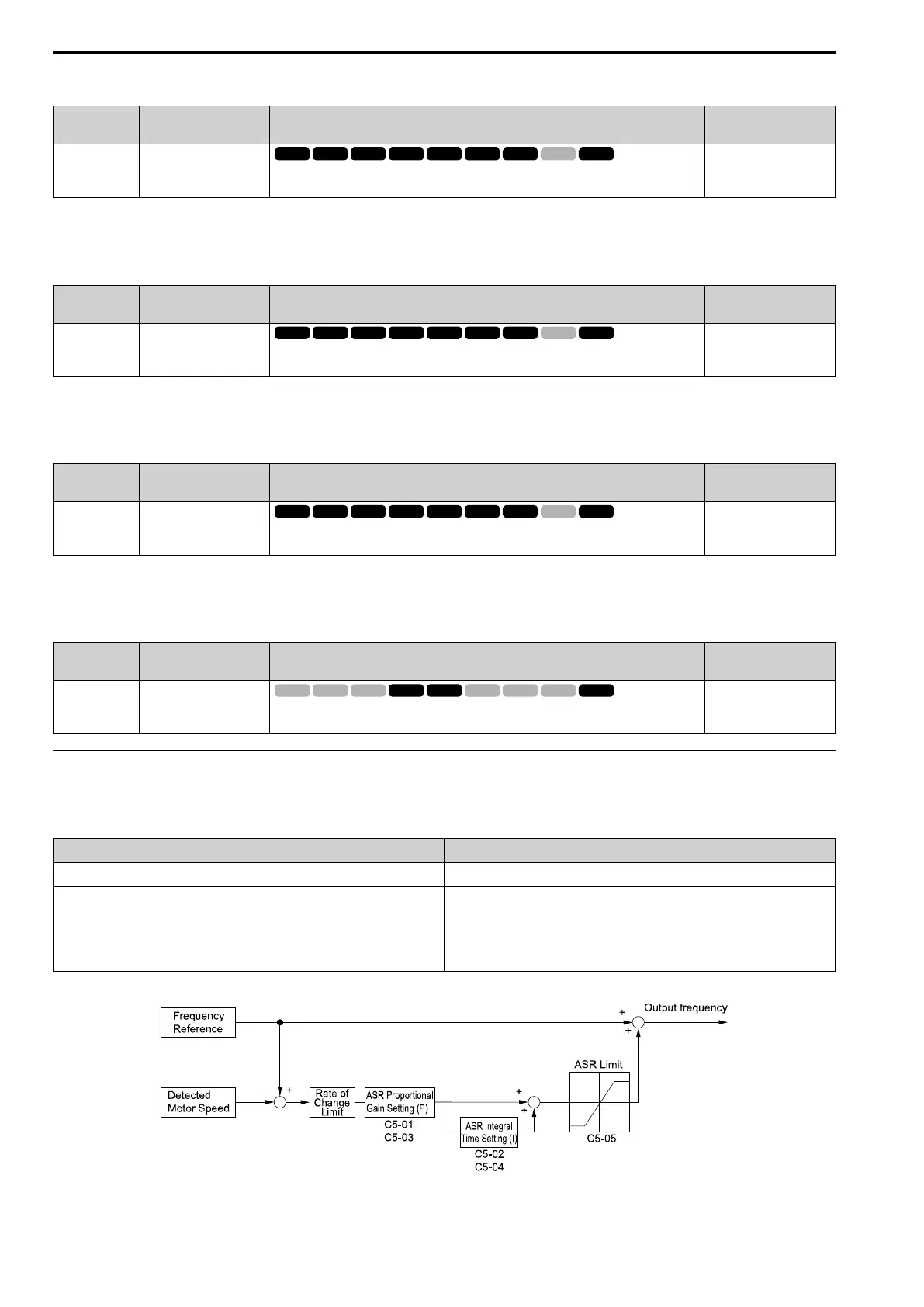
◆ C5: Automatic Speed Regulator (ASR: Automatic Speed Regulator)
The ASR adjusts the output frequency or torque reference to decrease the difference between frequency reference
and motor speed. The control method sets the parameter that you must adjust.
A1-02 [Control Method Selection] Targets of Adjustment
1: Closed Loop V/f Control (CL-V/f) Output frequency
• 3: Closed Loop Vector Control (CLV)
• 4: Advanced Open Loop Vector Control (AOLV)
• 6: PM Advanced Open Loop Vector (AOLV/PM)
• 7: Closed Loop Vector Control for PM (CLV/PM)
• 8: EZ Vector Control (EZOLV)
Torque Reference
Figure 12.54 and Figure 12.55 are speed control block diagrams of each control method.
Figure 12.54 Speed Control Block Diagram for CL-V/f

 Loading...


