11.12 n: Special Adjustment
562 YASKAWA SIEPC71061705H GA700 Series Technical Manual
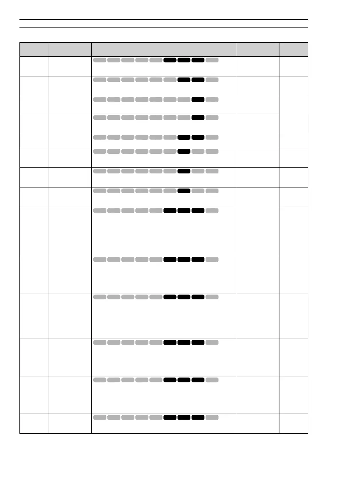
◆ n8: PM Motor Control Tuning
No.
(Hex.)
Name Description
Default
(Range)
Ref.
n8-01
(0540)
Expert
Pole Position Detection
Current
Sets the Initial Rotor Position Estimated Current as a percentage where E5-03 [PM
Motor Rated Current (FLA)] = 100%. Usually it is not necessary to change this setting.
50%
(0 - 100%)
933
n8-02
(0541)
Expert
Pole Alignment Current
Level
Sets the current at the time of polar attraction as a percentage where E5-03 [PM Motor
Rated Current (FLA)] = 100%. Usually it is not necessary to change this setting.
80%
(0 - 150%)
933
n8-03
(0542)
Pole Position Detection
Time
Sets the length of the Current Starting Time, which is used for Z Pulse Offset Tuning.
Usually it is not necessary to change this setting.
1.5 s
(1.5 - 5.0 s)
933
n8-04
(0543)
Expert
Pole Alignment Time
Sets the length of the Polar Attraction Time, which is used for Z Pulse Offset Tuning.
Usually it is not necessary to change this setting.
1.5 s
(1.5 - 5.0 s)
933
n8-11
(054A)
Observer Calculation
Gain 2
Sets the gain for speed estimation. Usually it is not necessary to change this setting.
Determined by n8-72
(0.0 - 1000.0)
933
n8-14
(054D)
Expert
Polarity Compensation
Gain 3
Sets the gain for speed estimation. Usually it is not necessary to change this setting.
1.000
(0.000 - 10.000)
934
n8-15
(054E)
Expert
Polarity Compensation
Gain 4
Sets the gain for speed estimation. Usually it is not necessary to change this setting.
0.500
(0.000 - 10.000)
934
n8-21
(0554)
Expert
Motor Back-EMF (Ke)
Gain
Sets the gain for speed estimation. Usually it is not necessary to change this setting.
0.90
(0.80 - 1.00)
934
n8-35
(0562)
Initial Pole Detection
Method
Sets how the drive detects the position of the rotor at start.
Note:
• When you operate an SPM motor, set n8-35 = 0. When you operate an IPM motor,
you can set n8-35 = 0 to 2.
• When you set n8-35 = 1, doHigh Frequency Injection Auto-Tuning.
0 : Pull-in
1 : High Frequency Injection
2 : Pulse Injection
Determined by A1-02
(0 - 2)
934
n8-36
(0563)
HFI Frequency Level for
L Tuning
Sets the injection frequency for high frequency injection.
Note:
• Set n8-35 = 1 [Initial Pole Detection Method = High Frequency Injection] or n8-
57 = 1 [HFI Overlap Selection = Enabled] to enable this parameter.
• The drive automatically calculates this value when High Frequency Injection
Auto-Tuning completes successfully.
500 Hz
(200 - 1000 Hz)
934
n8-37
(0564)
Expert
HFI Voltage Amplitude
Level
Sets the high frequency injection amplitude as a percentage where 200 V = 100% for
200 V class drives and 400 V = 100% for a 400 V class drives. Usually it is not
necessary to change this setting.
Note:
• Set n8-35 = 1 [Initial Pole Detection Method = High Frequency Injection] or n8-
57 = 1 [HFI Overlap Selection = Enabled] to enable this parameter.
• The drive automatically calculates this value when High Frequency Injection
Auto-Tuning completes successfully.
20.0%
(0.0 - 50.0%)
935
n8-39
(0566)
HFI LPF Cutoff Freq
Sets the low-pass filter shut-off frequency for high frequency injection.
Note:
• Set n8-35 = 1 [Initial Pole Detection Method = High Frequency Injection] or n8-
57 = 1 [HFI Overlap Selection = Enabled] to enable this parameter.
• The drive automatically calculates this value when High Frequency Injection
Auto-Tuning completes successfully.
250 Hz
(0 - 1000 Hz)
935
n8-41
(0568)
Expert
HFI P Gain
Sets the response gain for the high frequency injection speed estimation.
Note:
• Set n8-35 = 1 [Initial Pole Detection Method = High Frequency Injection] or n8-
57 = 1 [HFI Overlap Selection = Enabled] to enable this parameter.
• When A1-02= 6 [Control Method Selection = AOLV/PM] and you do High
Frequency Injection Auto-Tuning, the drive automatically sets this parameter .
2.5
(-10.0 - +10.0)
935
n8-42
(0569)
Expert
HFI I Time
Sets the integral time constant for the high frequency injection speed estimation.
Usually it is not necessary to change this setting.
0.10 s
(0.00 - 9.99 s)
935

 Loading...


