3.3 Main Circuit Wiring
74 YASKAWA SIEPC71061705H GA700 Series Technical Manual
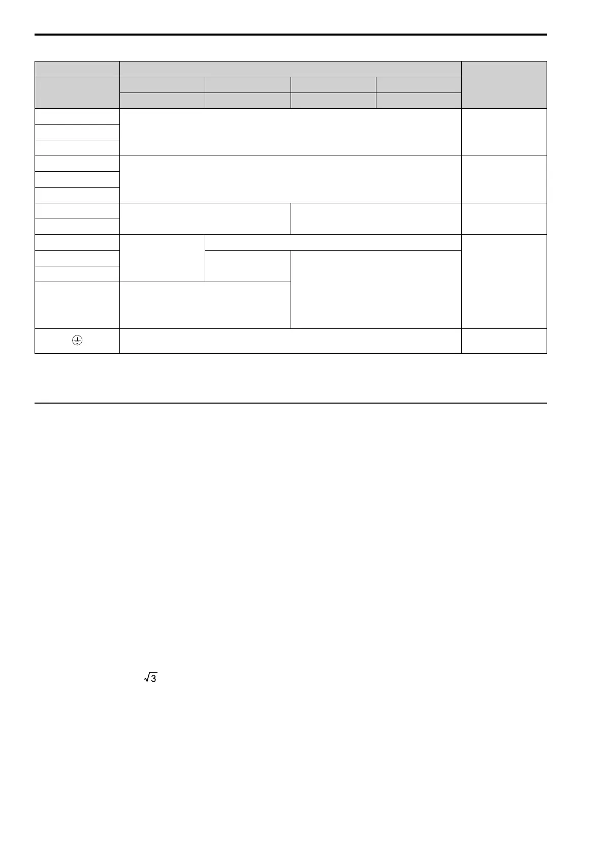
Table 3.2 Main Circuit Terminal Functions
Terminal Name
Function
Model
2004 - 2082 2110 - 2138 2169 - 2415 -
4002 - 4044 4060 - 4168 4208 - 4389 4453 - 4675
R/L1
Main circuit power supply input
To connect a commercial
power supply.
S/L2
T/L3
U/T1
Drive output To connect a motor.V/T2
W/T3
B1
Braking resistor connection -
To connect a braking
resistor or braking resistor
unit.
B2
+2
• DC power supply input
(+1 and -)
• DC reactor connection
(+1 and +2)
-
To connect peripheral
devices, for example:
• DC power input
• Braking Unit
• DC reactor
Note:
Remove the jumper
between terminals +1
and +2 to connect a DC
reactor.
+1
DC power supply input (+1
and -)
• DC power supply input (+1 and -)
• Braking unit connection (+3 and -)
-
+3 -
• 200 V: D class grounding (ground to 100 Ω or less)
• 400 V: C class grounding (ground to 10 Ω or less)
To ground the drive.
Note:
Use terminals - and B1 to connect a CDBR-type control unit to drive models 2004 to 2138 and 4002 to 4168 that have built-in braking
transistors.
◆ Wire Selection
Select the correct wires for main circuit wiring.
Refer to Main Circuit Wire Gauges and Tightening Torques on page 218 for wire gauges and tightening torques as
specified by European standards.
Refer to Main Circuit Wire Gauges and Tightening Torques on page 243 for wire gauges and tightening torques as
specified by UL standards.
■ Wire Selection Precautions
WARNING! Crush Hazard.
Make sure that the protective ground wire complies with technical standards and local safety regulations. The IEC/EN 61800-5-
1:2007 standard specifies that you must wire the power supply to automatically de-energize when the protective ground wire
disconnects. You can also connect a protective ground wire that has a minimum cross-sectional area of 10mm
2
(copper wire) or
16 mm
2
(aluminum wire). The leakage current of the drive will be more than 3.5 mA in drive models;
• 2xxxB
• 2xxxC
• 4002B to 4371B
• 4002C to 4371C (with built-in EMC filter turned ON)
• 4389 to 4675
If you do not obey the standards and regulations, it can cause serious injury or death.
Think about line voltage drop before selecting wire gauges. Select wire gauges that drop the voltage by 2% or less
of the rated voltage. Increase the wire gauge and the cable length when the risk of voltage drops increases.
Calculate line voltage drop with this formula:
Line voltage drop (V) = × wire resistance (Ω/km) × wiring distance (m) × motor rated current (A) × 10
-3
.
■ Precautions during Wiring
• Use terminals B1 and - to connect braking units to drives that have built-in braking transistors (models 2004 to
2138 and 4002 to 4168). Use terminals +3 and - to connect braking units to drives that do not have built-in
braking transistors.
• Refer to “Yaskawa AC Drive Option Braking Unit, Braking Resistor Unit Instruction Manual
(TOBPC72060001)” for information about wire gauges and tightening torques to connect braking resistor units
or braking units.

 Loading...


