5.2 European Standards
218 YASKAWA SIEPC71061705H GA700 Series Technical Manual
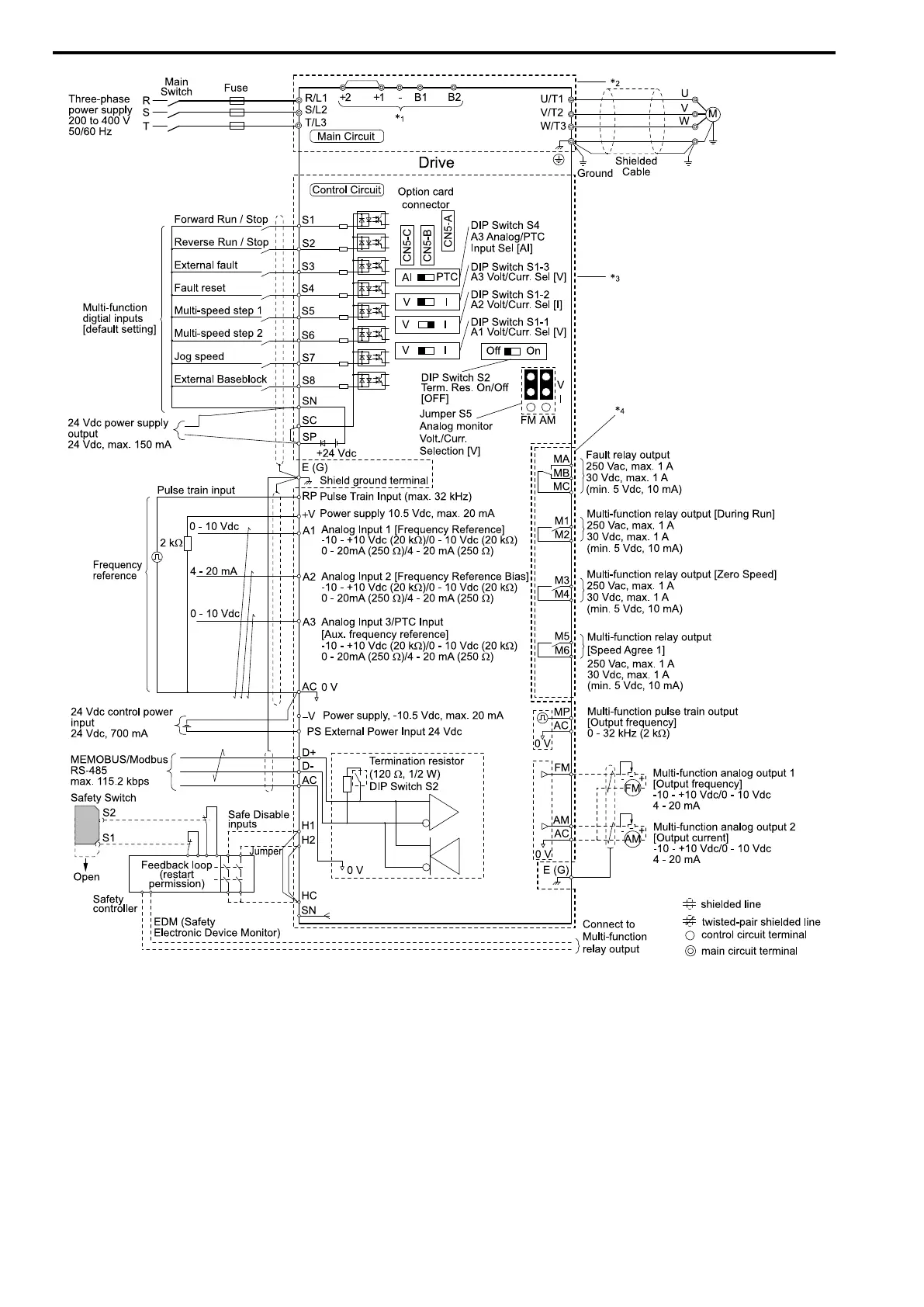
Figure 5.2 Wiring Diagram for CE Low Voltage Directive Compliance
*1 Connect peripheral options to terminals -, +1, +2, B1, and B2.
WARNING! Sudden Movement Hazard. Make sure that the polarity is correct before you send a Run command. If the
drive incorrectly detects the polarity, the drive can rotate in the direction opposite of the Run command and cause serious
injury or death.
*2 To protect the circuit, the main circuit is separate from the surface case that can touch the main circuit.
*3 The control circuit is a Safety Extra-Low Voltage circuit. Use reinforced insulation to separate this circuit from other circuits. Make
sure that you connect the Safety Extra-Low Voltage as specified.
*4 Reinforced insulation separates the output terminals from other circuits. You can also connect circuits that are not Safety Extra-Low
Voltage circuits when the drive output is 250 Vac 1 A maximum or 30 Vdc 1 A maximum.
■ Main Circuit Wire Gauges and Tightening Torques
WARNING! Electrical Shock Hazard. Only connect peripheral options, for example a DC reactor or braking resistor, to terminals
+1, +2, +3, -, B1, and B2. Incorrect wiring can cause serious injury or death.

 Loading...


