Network Communications
6
6.3 MEMOBUS/Modbus Communications
YASKAWA SIEPC71061705H GA700 Series Technical Manual 309
Minor Fault/
Alarm Code
(Hex.)
Name
0042 TrPC [IGBT Maintenance Time (90%)]
0043 LT-3 [SoftChargeBypassRelay MainteTime]
0044 LT-4 [IGBT Maintenance Time (50%)]
0045 boL [Braking Transistor Overload]
0049 dWAL [DriveWorksEZ Alarm]
004A dWA2 [DriveWorksEZ Alarm 2]
004B dWA3 [DriveWorksEZ Alarm 3]
Minor Fault/
Alarm Code
(Hex.)
Name
0081
EP24v [External Power 24V Supply]
0085
bAT [Keypad Battery Low Voltage]
0087
CP1 [Comparator 1 Limit Error]
0088
CP2 [Comparator 2 Limit Error]
0089
TiM [Keypad Time Not Set]
008A
bCE [Bluetooth Communication Error]
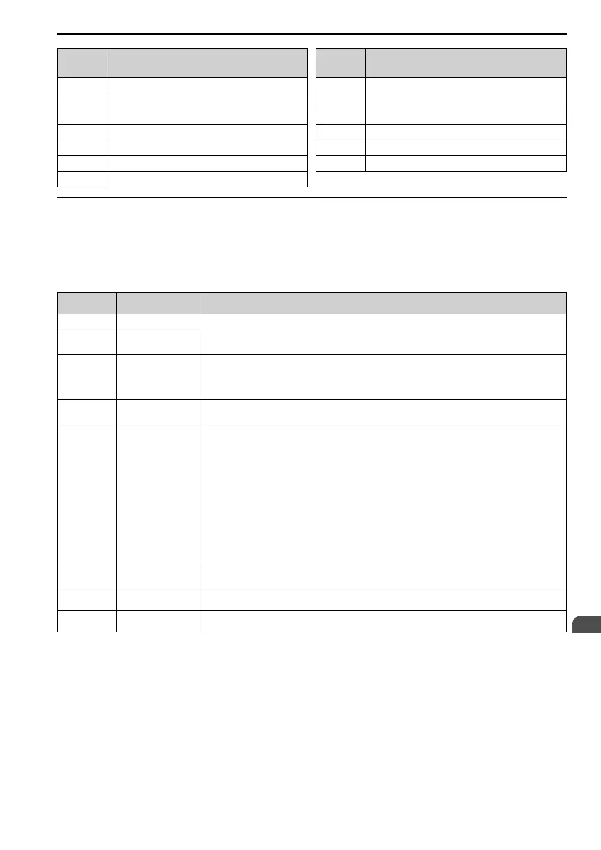
◆ Error Codes
■ MEMOBUS/Modbus Communications Error Code List
Table 6.20 lists the MEMOBUS/Modbus communications error codes.
When an error occurs, remove the cause of the error and restart communications.
Table 6.20 MEMOBUS/Modbus Communications Error Codes
Error Code
(Hex.)
Name Cause
01 Function Code Error The PLC set a function code that was not 03, 08, or 10 (Hex.)
02 Register Number Error
• The register number that is trying to access is not registered.
• A starting number that was not 0001 or 0002 (Hex.) was set when broadcasting.
03 Bit Count Error
• Read and write data quantities are more than the 1 to 16 range. (Command message data quantity is disabled.)
• The data that was read from non-consecutive holding registers contained more than 120 bytes.
• The data to be written to non-consecutive holding registers contained more than 60 bytes.
• In the write mode, the number of bytes in the message is not the number of data × 2.
21 Data Setting Error
• Writing control data or parameters made the settings go out of the permitted setting range.
• A parameter setting error occurred when writing a parameter.
22 Write Mode Error
• Tried to write a disabled parameter during run.
• When there was a CPF06 [Control Circuit Error], the master tried to write a parameter other than one of these:
– A1-00 [Language Selection]
– A1-01 [Access Level Selection]
– A1-02 [Control Method Selection]
– A1-03 [Initialize Parameters]
– A1-04 [Password]
– A1-05 [Password Setting]
– E1-03 [V/f Pattern Selection]
– o2-04 [Drive Model (KVA) Selection]
• Writes the read-only data.
23
DC Bus Undervoltage
Write Error
During Uv [DC Bus Undervoltage], a Uv write disabled parameter was written.
24
Error Writing Data During
Parameter Processing
Tried to write a parameter from the master during parameter processing on the drive side.
25
Writing into EEPROM
Disabled
Writing into EEPROM write is disabled, but EEPROM write was executed from MEMOBUS/Modbus communications. When
this error occurs, the keypad shows a message and the drive continues operation.
■ No Response from Slave
The slave ignores the command message from the master and will not send a response message in these
conditions:
• When a communications error (overrun, framing, parity, CRC-16) is detected in the command message.
• When the slave address in the command message and the slave address for the drive side do not agree (Use H5-
01 [Drive Node Address] to set the slave address of the drive)
• When the time interval between the data of which the message is composed is longer than 24 bits
• When the data length for the command message is not accurate

 Loading...


