3.3 Main Circuit Wiring
84 YASKAWA SIEPC71061705H GA700 Series Technical Manual
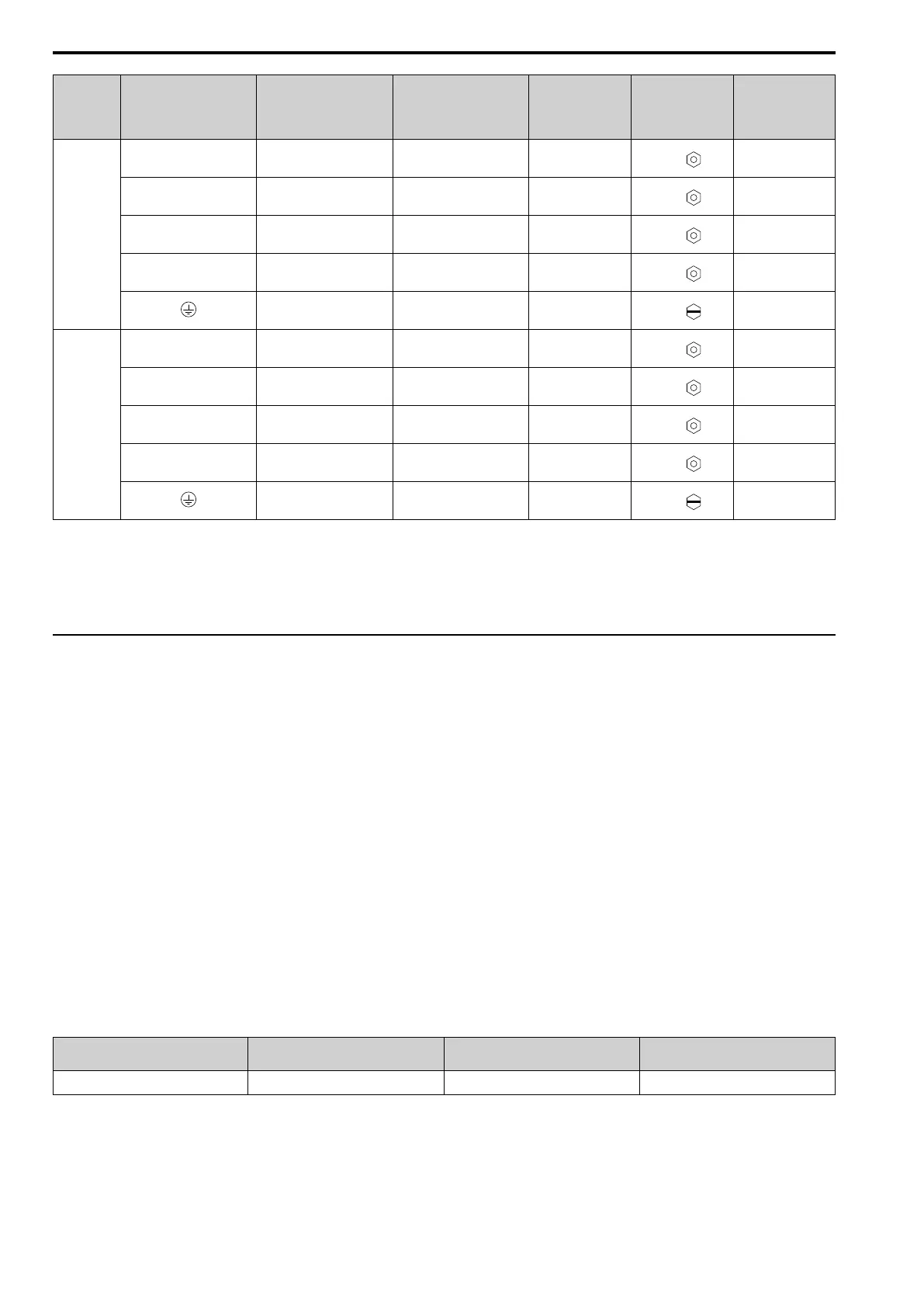
Model Terminal
Recomm. Gauge
mm
2
Applicable Gauge
(IP20 Applicable Gauge
*1
)
mm
2
Wire Stripping
Length
*2
mm
Terminal Screw
Size and Shape
Tightening Torque
N∙m (lbf∙in)
4568
R/L1, S/L2, T/L3 120 × 4P
70 - 150 × 4P
(150 × 4P)
-
M12
35
(310)
U/T1, V/T2, W/T3 95 × 4P
70 - 150 × 4P
(120 - 150 × 4P)
-
M12
35
(310)
-, +1 95 × 4P
95 - 185 × 4P
(185 × 4P)
-
M12
35
(310)
+3 70 × 4P
35 - 95 × 4P
(95 × 4P)
-
M12
35
(310)
95 × 2P
60 - 150
(-)
-
M12
32 - 40
(283 - 354)
4675
R/L1, S/L2, T/L3 120 × 4P
70 - 150 × 4P
(150 × 4P)
-
M12
35
(310)
U/T1, V/T2, W/T3 95 × 4P
70 - 150 × 4P
(120 - 150 × 4P)
-
M12
35
(310)
-, +1 95 × 4P
95 - 185 × 4P
(185 × 4P)
-
M12
35
(310)
+3 70 × 4P
35 - 95 × 4P
(95 × 4P)
-
M12
35
(310)
95 × 2P
60 - 150
(-)
-
M12
32 - 40
(283 - 354)
*1 For IP20 protection, use wires that are in the range of applicable gauges.
*2 Remove insulation from the ends of wires to expose the length of wire shown.
*3 For wire gauges more than 30 mm
2
, tighten to a tightening torque of 4.1 N∙m to 4.5 N∙m (36 lbf∙in to 40 lbf∙in).
*4 Install an RCM/RCD with this wire gauge to maintain compliance with IEC/EN 61800-5-1:2007.
*5 Terminals - and +1 have two screws. The Recommended Gauge is the wire gauge for one terminal.
*6 A junction terminal is necessary to connect a braking resistor unit (LKEB-series) to terminals B1 and B2.
◆ Main Circuit Terminal and Motor Wiring
This section outlines the various steps, precautions, and checkpoints for wiring the main circuit terminals and
motor terminals.
WARNING! Fire Hazard. Do not connect main power supply wiring to drive motor terminals U/T1, V/T2, and W/T3. Connect
main power supply wiring to main circuit input terminals R/L1, S/L2, and T/L3. Incorrect wiring can cause serious injury or death
from fire.
WARNING! Sudden Movement Hazard. Make sure that you align the phase order for the drive and motor when you connect the
motor to drive output terminals U/T1, V/T2, and W/T3. If the phase order is incorrect, it can cause the motor to run in reverse. If
the motor accidentally runs in reverse, it can cause serious injury or death.
NOTICE: Do not connect phase-advancing capacitors, LC/RC noise filters, or leakage breakers (RCM/RCD) to the motor
circuit. If you connect these devices to the output circuits, it can cause damage to the drive and connected equipment.
■ Cable Length Between Drive and Motor
When the wiring between the drive and the motor is too long, voltage drop along the motor cable can decrease
motor torque, usually at low frequency output. If you connect motors in parallel with long motor cable, this is also
a problem. Drive output current increases when the leakage current from the cable increases. An increase in
leakage current can cause overcurrent and decrease the precision of the current detection.
Use the values in Table 3.3 to adjust the drive carrier frequency. For systems that have 100 m (328 ft) or longer
motor wiring, if you use metal conduits or isolated cables for each phase, it will increase stray capacitance.
Table 3.3 Carrier Frequency against Cable Length Between Drive and Motor
Wiring Distance Between the Drive
and Motor
50 m (164 ft) Maximum 100 m (328 ft) Maximum More than 100 m (328 ft)
Carrier Frequency 15 kHz or less 5 kHz or less 2 kHz or less
Note:
• To set the carrier frequency in a drive that is operating more than one motor, calculate the cable length as the total distance of wiring to
all connected motors.
• When A1-02 = 5, 6 [OLV/PM, AOLV/PM], the maximum cable length is 100 m (328 ft).
• When you connect to a PM motor, it can be necessary to adjust the overcurrent detection. Refer to L8-27: Overcurrent Detection Gain
on page 913 for more information.

 Loading...


