7.10 Troubleshooting Without Fault Display
374 YASKAWA SIEPC71061705H GA700 Series Technical Manual
Causes Possible Solutions
You entered an incorrect password in A1-04 [Password]. • Enter the correct password to A1-04 again.
• If you forgot the password, set the password again with A1-04 and A1-05 [Password Setting].
Note:
If you set the password, you cannot change these parameters until the password aligns:
• A1-01 [Access Level Selection]
• A1-02 [Control Method Selection]
• A1-03 [Initialize Parameters]
• A1-06 [Application Preset]
• A1-07 [DriveWorksEZ Function Selection]
• A2-01 to A2-32 [User Parameter 1 to User Parameter 32]
The drive detected Uv [Undervoltage]. • View U1-07 [DC Bus Voltage] to see the power supply voltage.
• Examine the main circuit wiring.
◆ The Motor Does Not Rotate After Entering Run Command
Causes Possible Solutions
The drive is not in Drive Mode. 1. Make sure that the keypad shows [Rdy].
2. If the keypad does not show [Rdy], go back to the Home screen.
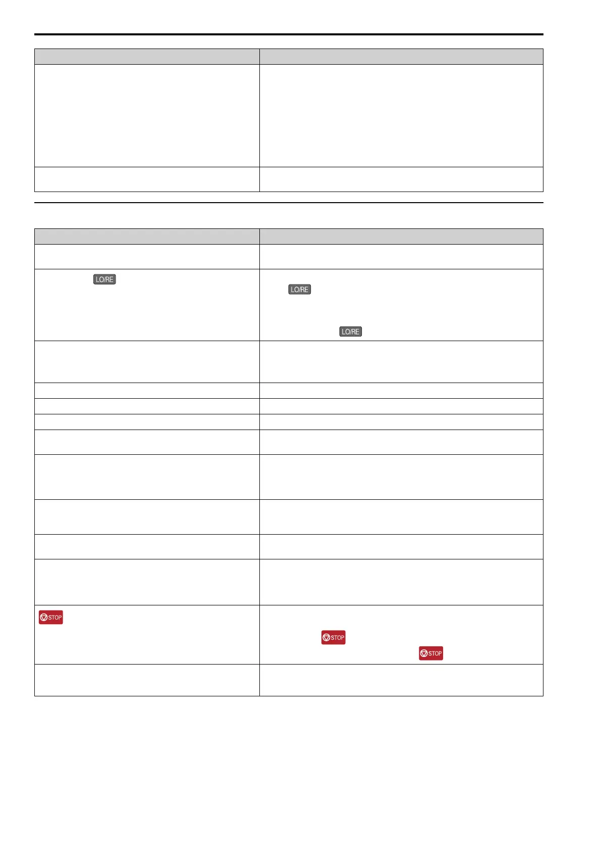
The drive stopped, was pushed, and changed the Run command
source to the keypad.
Do one of these two:
• Push .
• Re-energize the drive.
Note:
Set o2-01 = 0 [LO/RE Key Function Selection = Disabled] to prevent changing the Run
command source with .
Auto-Tuning completed. Go back to the Home screen on the keypad.
Note:
When Auto-Tuning completes, the drive changes to Programming Mode. The drive will not
accept a Run command unless the drive is in Drive Mode.
The drive received a fast stop command. Turn off the fast stop input signal.
The settings for the source that supplies the Run command are incorrect. Set b1-02 [Run Command Selection 1] correctly.
The frequency reference source is set incorrectly. Set b1-01 [Frequency Reference Selection 1] correctly.
There is defective wiring in the control circuit terminals. • Correctly wire the drive control circuit terminals.
• View U1-10 [Input Terminal Status] for input terminal status.
The settings for voltage input and current input of the master frequency
reference are incorrect.
Examine these analog input terminal signal level settings:
• Terminal A1: DIP switch S1-1 and H3-01 [Terminal A1 Signal Level Select]
• Terminal A2: DIP switch S1-2 and H3-09 [Terminal A2 Signal Level Select]
• Terminal A3: DIP switch S4, S1-3 and H3-05 [Terminal A3 Signal Level Select]
The selection for the sinking/sourcing mode and the internal/external power
supply is incorrect.
• For sinking mode, close the circuit between terminals SC-SP with a wire jumper.
• For sourcing mode, close the circuit between terminals SC-SN with a wire jumper.
• For external power supply, remove the wire jumper.
The frequency reference is too low. • View U1-01 [Freq Reference].
• Increase the frequency reference to a value higher than E1-09 [Minimum Output Frequency].
The MFAI setting is incorrect. • Make sure that the functions set to the MFAI are correct. The frequency reference is 0 when
H3-02, H3-10, H3-06 = 1 [MFAI Function Select = Frequency Gain] and voltage (current) is
not input.
• View U1-13 to U1-15 [Terminal A1, A2, A3 Input Voltage] to see if the analog input values set
to terminals A1, A2, and A3 are applicable.
was pushed.
Turn the Run command OFF then ON from an external input.
Note:
When you push during operation, the drive will ramp to stop. Set o2-02 = 0 [STOP
Key Function Selection = Disabled] to disable the function.
The 2-wire sequence and 3-wire sequence are set incorrectly. • Set one of the parameters H1-03 to H1-08 [Terminals S3 to S8 Function Select] to 0 [3-Wire
Sequence] to enable the 3-wire sequence.
• If a 2-wire sequence is necessary, make sure that H1-03 to H1-08 ≠ 0.

 Loading...


