Troubleshooting
7
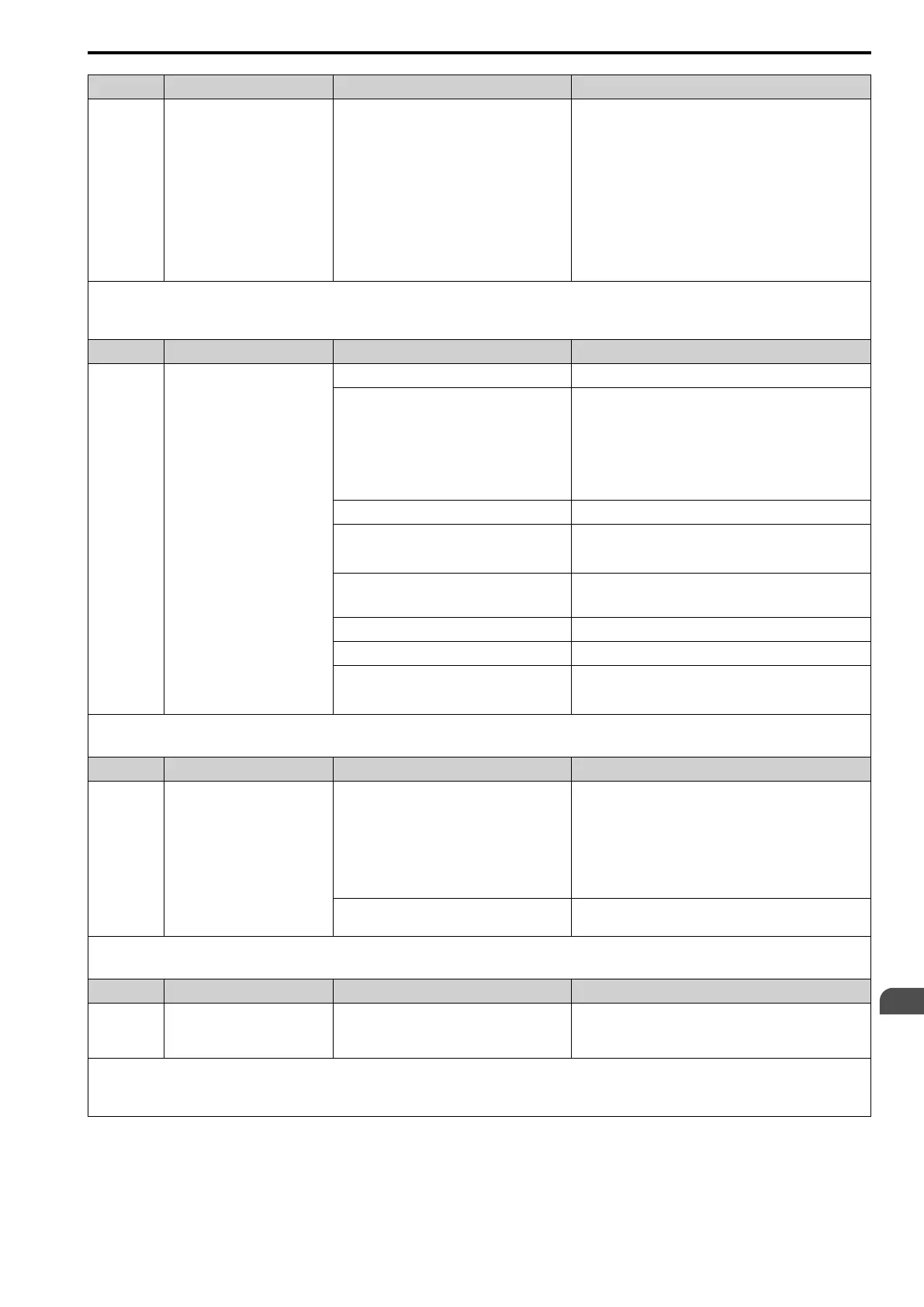
7.4 Fault
YASKAWA SIEPC71061705H GA700 Series Technical Manual 321
Code Name Causes Possible Solutions
Electrical interference caused a communication data
error.
• Examine the control circuit lines, main circuit lines, and
ground wiring, and decrease the effects of electrical
interference.
• Make sure that a magnetic contactor is not the source of the
electrical interference, then use a Surge Protective Device if
necessary.
• Use only the recommended cables or other shielded line.
Ground the shield on the controller side or the drive input
power side.
• Separate the communication wiring from drive power lines,
and install a noise filter to the input side of the power supply
for communication.
• Decrease the effects of electrical interference from the
controller.
Note:
• The drive detects this error if it does not correctly receive control data for the CE detection time set to H5-09 [CE Detection Time].
• Do a Fault Reset to clear the fault.
• If the drive detects this error, the drive will operate the motor as specified by the stopping method set in H5-04 [Communication Error Stop Method].
Code Name Causes Possible Solutions
CF Control Fault
Motor parameters are set incorrectly Correctly set the motor parameters and do Auto-Tuning again.
When A1-02 = 4 [Control Method Selection =
Advanced Open Loop Vector], the drive takes long
to ramp to stop because of these settings:
• The torque limit setting is too low.
• L3-11 = 1 [Overvoltage Suppression Select =
Enabled].
• d5-01 = 1 [Torque Control Selection = Torque
Control].
When Rotational Auto-Tuning changes or the installation
environment changes, make sure that you do Line-to-Line
Resistance Tuning and set L8-20 = 0 [Control Fault & Step Out
Detect = Disabled].
Note:
After you set L8-20 = 0, do test runs and examine the drive to
make sure that it starts and stops correctly.
The torque limit setting is too low. Adjust L7-01 to L7-04 [Torque Limit].
The load inertia is too large. • Adjust C1-02, C1-04, C1-06, and C1-08 [Deceleration Times].
• Set the frequency reference to the minimum output frequency,
and stop the Run command when the drive stops deceleration.
The drive is trying to ramp to stop a machine that
cannot do ramp to stop or on a machine for which
deceleration is not necessary.
Correctly set b1-03 [Stopping Method Selection].
The motor and drive are connected incorrectly. Correct wiring errors.
Line-to-line Resistance Tuning is not done. Do Stationary Auto-Tuning for Line-to-Line Resistance.
The drive received a Run command while the motor
was coasting.
• Examine the sequence and input the Run command after the
motor fully stops.
• Set b3-01 = 1 [Speed Search at Start Selection = Enabled].
Note:
• The drive detects this error if the torque reference is more than the torque limit for 3 seconds or longer while the drive ramps to stop.
• Do a Fault Reset to clear the fault.
Code Name Causes Possible Solutions
CoF Current Offset Fault
The drive starts operation while the induced voltage
stays in the motor (during coasting to a stop or after
fast deceleration).
• Make a sequence that does not restart operation when induced
voltage stays in the motor.
• Set b3-01 = 1 [Speed Search at Start Selection = Enabled].
• Use Speed Search from Fmax or Fref [H1-xx = 61, 62] to do a
speed search through one of the external terminals.
Note:
When controlling the PM motor, External Speed Search
commands 1 and 2 operate the same.
A drive hardware problem occurred. • Do a Fault Reset to clear the fault or de-energize the drive.
• If the fault stays, replace the drive
Note:
• The drive detects this error if the current offset value is more than the permitted setting range while the drive automatically adjusts the current offset.
• Do a Fault Reset to clear the fault.
Code Name Causes Possible Solutions
CP1 Comparator 1 Limit Fault
The monitor value set in H2-20 [Comparator 1
Monitor Selection] was in the range of H2-21
[Comparator 1 Lower Limit] and H2-22
[Comparator 1 Upper Limit].
Examine the monitor value and remove the cause of the fault.
Note:
• The drive detects this error when the terminal is set to H2-01 to H2-03 = 66 [MFDO Function Selection = Comparator1].
• Do a Fault Reset to clear the fault.
• Set the stopping method for this fault in H2-33 [Comparator1 Protection Selection].

 Loading...


