3.2 Electrical Installation
66 YASKAWA SIEPC71061705H GA700 Series Technical Manual
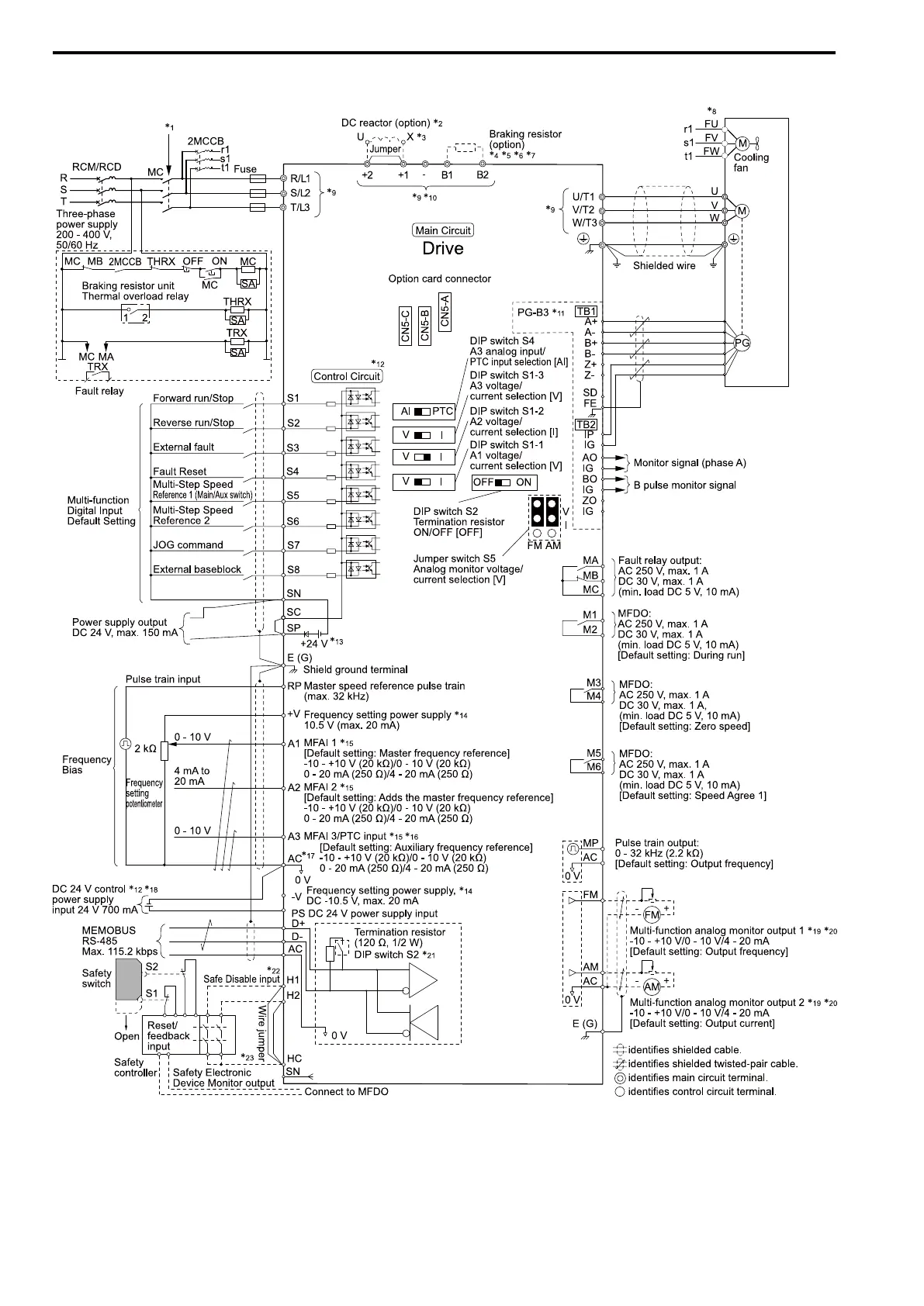
■ Standard Drive Connection Diagram
Figure 3.1 Standard Drive Connection Diagram
*1 Set the wiring sequence to de-energize the drive with the fault relay output. If the drive outputs a fault during fault restart when you
use the fault restart function, set L5-02 = 1 [Fault Contact at Restart Select = Always Active] to de-energize the drive. Be careful
when you use a cut-off sequence. The default setting for L5-02 is 0 [Active Only when Not Restarting].
*2 When you install a DC reactor, you must remove the jumper between terminals +1 and +2. Ground the DC reactor (option) on the
back of the mounting base. Remove all paint from the mounting surface of the control panel.

 Loading...


