12.8 H: Terminal Functions
816 YASKAWA SIEPC71061705H GA700 Series Technical Manual
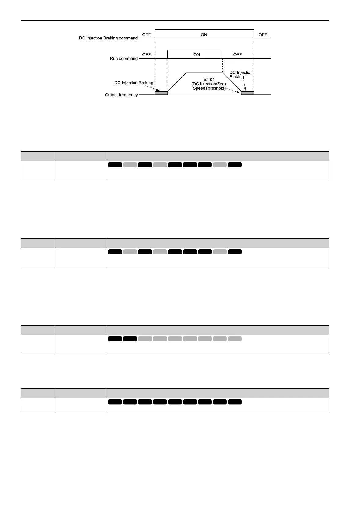
Figure 12.88 DC Injection Braking Time Chart
Note:
• When A1-02 = 8 [Control Method Selection = EZOLV], this function is available with a PM motor.
• Refer to b2: DC Injection Braking and Short Circuit Braking on page 654 for more information.
■ 61: Speed Search from Fmax
Setting Value Function Description
61 Speed Search from Fmax
Sets the function to use an external reference to start speed search although b3-01 = 0 [Speed Search Selection at Start =
Disabled] to not allow speed search at start.
When the terminal is activated for b3-24 = 2 [Speed Search Method Selection = Current Detection 2], the drive
starts speed search from the maximum output frequency.
Note:
• The drive will detect oPE03 [Multi-Function Input Setting Err] if you set H1-xx = 61 and 62 at the same time.
• Refer to “b3: Speed Search” for more information.
■ 62: Speed Search from Fref
Setting Value Function Description
62 Speed Search from Fref
Sets the function to use an external reference to start speed search although b3-01 = 0 [Speed Search Selection at Start =
Disabled] to not allow speed search at start.
When the terminal is activated for b3-24 = 2 [Speed Search Method Selection = Current Detection 2], the drive
starts speed search from the frequency reference.
Note:
• The drive will detect oPE03 [Multi-Function Input Setting Err] if you set H1-xx = 61 and 62 at the same time.
• Refer to “b3: Speed Search” for more information.
■ 63: Field Weakening
Setting Value Function Description
63 Field Weakening
Sets the function to send the Field Weakening Level and Field Weakening Frequency Limit commands set in d6-01 [Field
Weakening Level] and d6-02 [Field Weakening Frequency Limit] when the input terminal is activated.
Note:
Refer to d6: Field Weakening /Forcing on page 736 for more information.
■ 65: KEB Ride-Thru 1 Activate (N.C.)
Setting Value Function Description
65 KEB Ride-Thru 1 Activate
(N.C.)
Sets operation of the KEB1 function through the KEB Ride-Thru 1 (N.C.).
ON : Normal operation
OFF : Deceleration during momentary power loss
When you enable KEB Ride-Thru 1, set L2-29 [KEB Method Selection]. The drive operates with the selected
KEB method.
Note:
• If you set KEB Ride-Thru 1 [H1-xx = 65, 66] and KEB Ride-Thru 2 [H1-xx = 7A, 7B] at the same time, the drive will detect oPE03
[Multi-Function Input Setting Err].
• Refer to KEB Ride-Thru Function on page 877 for more information.

 Loading...


