Parameter Details
12
12.8 H: Terminal Functions
YASKAWA SIEPC71061705H GA700 Series Technical Manual 831
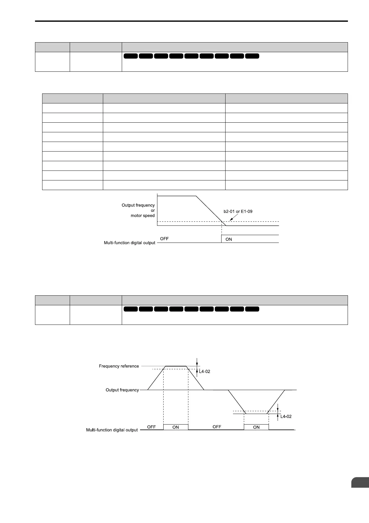
■ 1: Zero Speed
Setting Value Function Description
1 Zero Speed
The terminal activates when the output frequency < E1-09 [Minimum Output Frequency] or b2-01 [DC Injection/Zero
SpeedThreshold].
Note:
Parameter A1-02 [Control Method Selection] selects which parameter is the reference.
A1-02 Setting Control method selection Parameter Used as the Reference
0 V/f Control E1-09
1 V/f Control with Encoder E1-09
2 Open Loop Vector b2-01
3 Closed Loop Vector E1-09
4 Advanced OpenLoop Vector Control E1-09
5 PM Open Loop Vector E1-09
6 PM Advanced Open Loop Vector E1-09
7 PM Closed Loop Vector Control b2-01
8 EZ Open Loop Vector Control E1-09
Figure 12.93 Zero Speed Time Chart
ON : Output frequency < value of E1-09 or b2-01.
OFF : Output frequency ≥ value of E1-09 or b2-01.
■ 2: Speed Agree 1
Setting Value Function Description
2 Speed Agree 1
The terminal turns on when the output frequency is in the range of the frequency reference ± L4-02 [Speed Agree Detection
Width].
Note:
• The detection function operates in the two motor rotation directions.
• The drive outputs the motor speed status when A1-02 = 3, 7 [CLV, CLV/PM]. It also outputs the motor speed status when A1-02 = 4
and n4-72 = 1.
Figure 12.94 Speed Agree 1 Time Chart
ON : The output frequency is in the range of “frequency reference ± L4-02”.
OFF : The output frequency does not align with the frequency reference although the drive is
running.

 Loading...


