12.9 L: Protection Functions
894 YASKAWA SIEPC71061705H GA700 Series Technical Manual
Set one of these parameters to enable L3-20:
• L2-29 = 1 [Kinetic Energy Backup Method = Single Drive KEB Ride-Thru 2]
• L3-04 = 2 [Stall Prevention during Decel = Intelligent (Ignore Decel Ramp)]
• L3-11 = 1 [Overvoltage Suppression Select = Enabled]
• H1-xx = 7A or 7B [MFDI Function Selection = KEB Ride-Thru 2 Activate (N.O./N.C.)]
Note:
When Auto-Tuning changes the value of E2-11 [Motor Rated Power], the drive will automatically set L3-24 to the value for a Yaskawa
standard motor (4 poles). When you use a PM motor, the drive uses the value in E5-01 [PM Motor Code Selection] to change L3-24.
Automatically Adjust Parameters
When A1-02 = 3, 7 [Control Method Selection = CLV, CLV/PM], do Inertia Tuning. Parameters are automatically
adjusted.
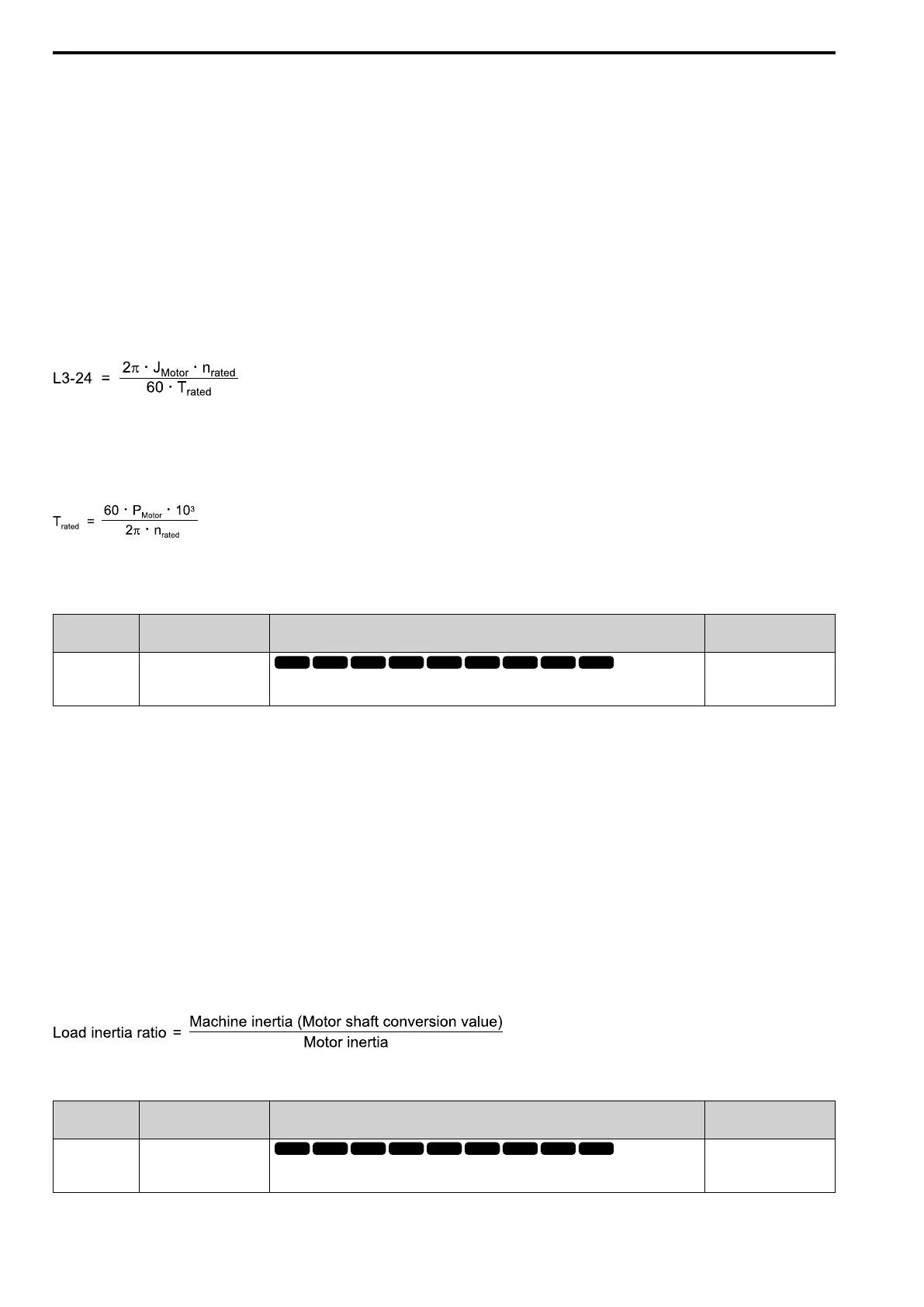
Manually Adjust Parameters
Use this formula to find the motor acceleration time:
• J
Motor
= Moment of inertia of motor (kg m
2
)
• n
rated
= Motor rated speed (min
-1
, r/min)
• T
rated
= Motor rated torque (N∙m)
The rated torque is calculated using the following expression.
P
Motor
= Motor Rated Power (kW)
■ L3-25: Load Inertia Ratio
No.
(Hex.)
Name Description
Default
(Range)
L3-25
(046F)
Expert
Load Inertia Ratio
Sets the ratio between motor inertia and machine inertia.
1.0
(0.1 - 1000.0)
Set one of these parameters to enable L3-20:
• L2-29 = 1 [Kinetic Energy Backup Method = Single Drive KEB Ride-Thru 2]
• L3-04 = 2 [Stall Prevention during Decel = Intelligent (Ignore Decel Ramp)]
• L3-11 = 1 [Overvoltage Suppression Select= Enabled]
• H1-xx = 7A or 7B [MFDI Function Selection = KEB Ride-Thru 2 Activate (N.O./N.C.)]
Note:
• If you set this value incorrectly when L2-29 = 1, H1-xx = 7A or 7B, or L3-11 = 1, it can cause large current ripples and ov
[Overvoltage], Uv1 [DC Bus Undervoltage], or oC [Overcurrent] faults.
• KEB Tuning will automatically set this value.
Automatically Adjust Parameters
When A1-02 = 3, 7 [Control Method Selection = CLV, CLV/PM], do Inertia Tuning. Parameters are automatically
adjusted.
Manually Adjust Parameters
Use this formula to find the load inertia ratio:
■ L3-26: Additional DC Bus Capacitors
No.
(Hex.)
Name Description
Default
(Range)
L3-26
(0455)
Expert
Additional DC Bus
Capacitors
Sets the capacity for external main circuit capacitors. Usually it is not necessary to change this
setting. Sets this parameter when you use the KEB Ride-Thru function.
0 μF
(0 to 65000 μF)

 Loading...


