6–36 Chapter 6: I/O Features in Cyclone IV Devices
High-Speed I/O Timing
Cyclone IV Device Handbook, March 2016 Altera Corporation
Volume 1
before the next edge; this may lead to pattern-dependent jitter. With pre-emphasis, the
output current is momentarily boosted during switching to increase the output slew
rate. The overshoot produced by this extra switching current is different from the
overshoot caused by signal reflection. This overshoot happens only during switching,
and does not produce ringing.
The Quartus II software allows two settings for programmable pre-emphasis
control—0 and 1, in which 0 is pre-emphasis off and 1 is pre-emphasis on. The default
setting is 1. The amount of pre-emphasis needed depends on the amplification of the
high-frequency components along the transmission line. You must adjust the setting
to suit your designs, as pre-emphasis decreases the amplitude of the low-frequency
component of the output signal.
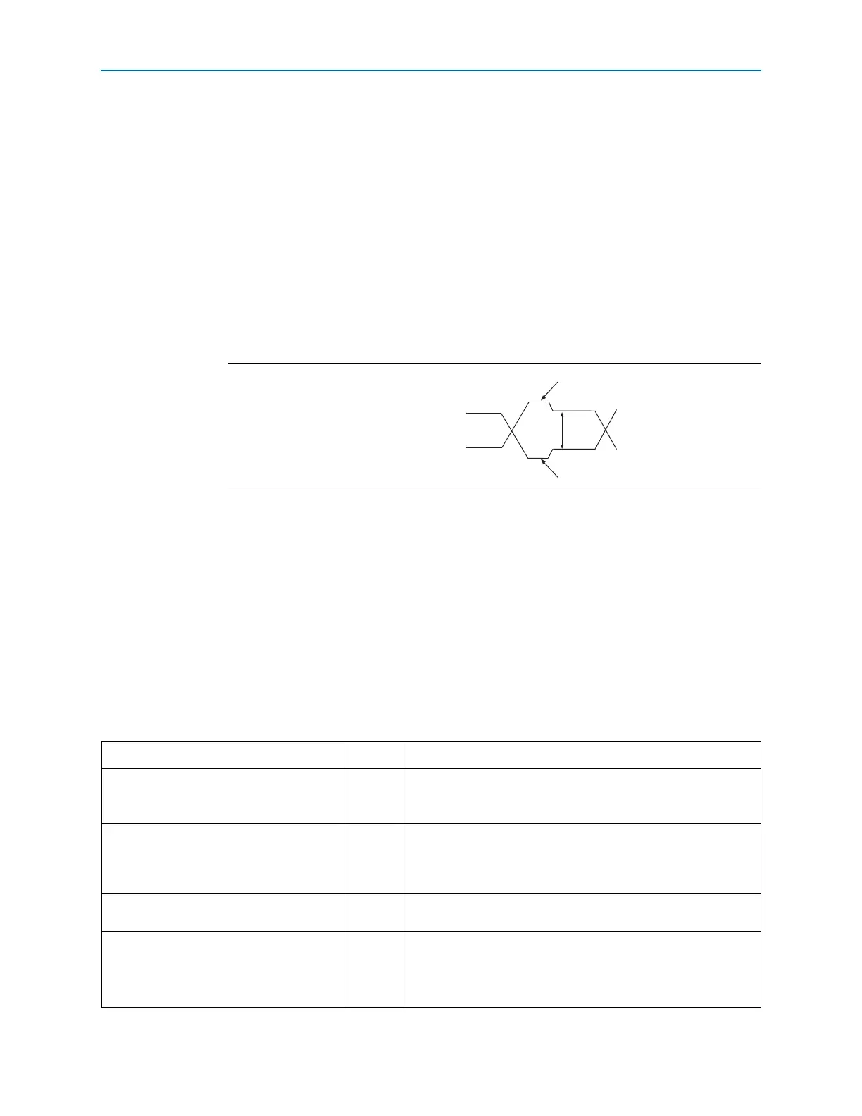
Figure 6–20 shows the differential output signal with pre-emphasis.
High-Speed I/O Timing
This section discusses the timing budget, waveforms, and specifications for
source-synchronous signaling in Cyclone IV devices. Timing for source-synchronous
signaling is based on skew between the data and clock signals.
High-speed differential data transmission requires timing parameters provided by IC
vendors and requires you to consider the board skew, cable skew, and clock jitter. This
section provides information about high-speed I/O standards timing parameters in
Cyclone IV devices.
Tab le 6 –11 defines the parameters of the timing diagram shown in Figure 6–21.
Figure 6–20. The Output Signal with Pre-Emphasis
V
OD
Positive channel (p)
Negative channel (n)
Overshoot
Undershoot
Table 6–11. High-Speed I/O Timing Definitions (Part 1 of 2)
Parameter Symbol Description
Transmitter channel-to-channel skew
(1)
TCCS
The timing difference between the fastest and slowest output
edges, including t
CO
variation and clock skew. The clock is
included in the TCCS measurement.
Sampling window SW
The period of time during which the data must be valid in order for
you to capture it correctly. The setup and hold times determine
the ideal strobe position in the sampling window.
T
SW
=T
SU
+T
hd
+ PLL jitter.
Time unit interval TUI
The TUI is the data-bit timing budget allowed for skew,
propagation delays, and data sampling window.
Receiver input skew margin RSKM
RSKM is defined by the total margin left after accounting for the
sampling window and TCCS. The RSKM equation is:
RSKM
TUI SW TCCS––
2
--------- ----------------- ------------- -----------
=