Chapter 8: Configuration and Remote System Upgrades in Cyclone IV Devices 8–79
Remote System Upgrade
May 2013 Altera Corporation Cyclone IV Device Handbook,
Volume 1
The remote system upgrade status register is updated by the dedicated error
monitoring circuitry after an error condition, but before the factory configuration is
loaded.
User Watchdog Timer
The user watchdog timer prevents a faulty application configuration from indefinitely
stalling the device. The system uses the timer to detect functional errors after an
application configuration is successfully loaded into the Cyclone IV device.
The user watchdog timer is a counter that counts down from the initial value loaded
into the remote system upgrade control register by the factory configuration. The
counter is 29 bits wide and has a maximum count value of 2
29
. When specifying the
user watchdog timer value, specify only the most significant 12 bits. The remote
system upgrade circuitry appends 17
'b1000 to form the 29-bits value for the watchdog
timer. The granularity of the timer setting is 2
17
cycles. The cycle time is based on the
frequency of the 10-MHz internal oscillator or
CLKUSR
(maximum frequency of
40 MHz).
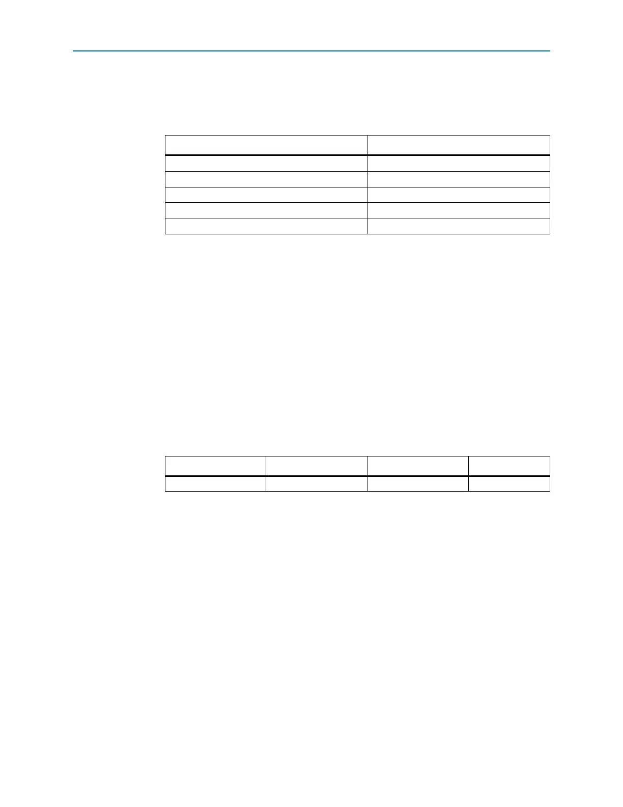
Tab le 8 –2 7 lists the operating range of the 10-MHz internal oscillator.
The user watchdog timer begins counting after the application configuration enters
device user mode. This timer must be periodically reloaded or reset by the application
configuration before the timer expires by asserting
RU_nRSTIMER
. If the application
configuration does not reload the user watchdog timer before the count expires, a
time-out signal is generated by the remote system upgrade dedicated circuitry. The
time-out signal tells the remote system upgrade circuitry to set the user watchdog
timer status bit (
Wd
) in the remote system upgrade status register and reconfigures the
device by loading the factory configuration.
1 To allow the remote system upgrade dedicated circuitry to reset the watchdog timer,
you must assert the
RU_nRSTIMER
signal active for a minimum of 250 ns. This is
equivalent to strobing the
reset_timer
input of the ALTREMOTE_UPDATE
megafunction high for a minimum of 250 ns.
Errors during configuration are detected by the CRC engine. Functional errors must
not exist in the factory configuration because it is stored and validated during
production and is never updated remotely.
Table 8–26. Control Register Contents After an Error or Reconfiguration Trigger Condition
Reconfiguration Error/Trigger Control Register Setting In Remote Update
nCONFIG
reset All bits are 0
nSTATUS
error All bits are 0
CORE triggered reconfiguration Update register
CRC error All bits are 0
Wd time out All bits are 0
Table 8–27. 10-MHz Internal Oscillator Specifications
Minimum Typical Maximum Unit
56.510MHz