Chapter 8: Configuration and Remote System Upgrades in Cyclone IV Devices 8–33
Configuration
May 2013 Altera Corporation Cyclone IV Device Handbook,
Volume 1
PS Configuration Using an External Host
In the PS configuration scheme, you can use an intelligent host such as a MAX II
device or microprocessor that controls the transfer of configuration data from a
storage device, such as flash memory, to the target Cyclone IV device. You can store
the configuration data in .rbf, .hex, or .ttf format.
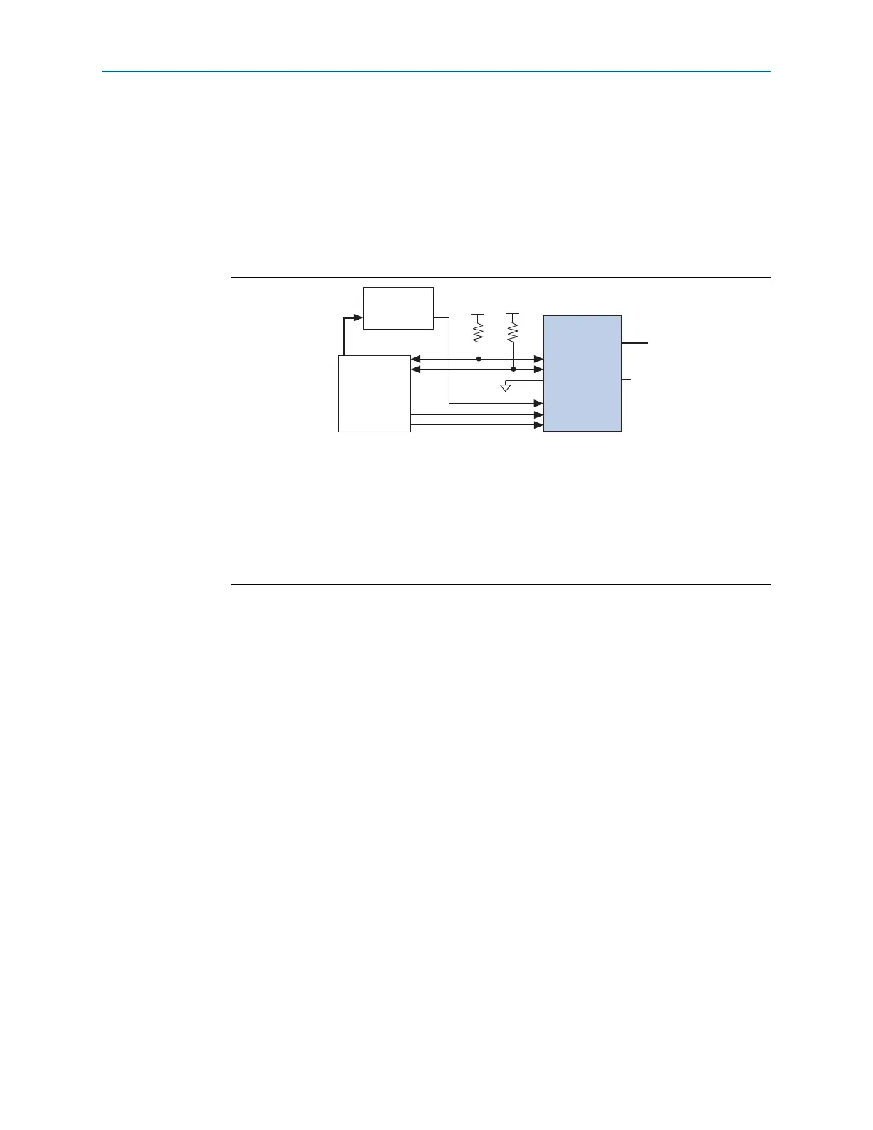
Figure 8–13 shows the configuration interface connections between a Cyclone IV
device and an external host device for single-device configuration.
To begin the configuration, the external host device must generate a low-to-high
transition on the
nCONFIG
pin. When
nSTATUS
is pulled high, the external host device
must place the configuration data one bit at a time on
DATA[0]
. If you use
configuration data in .rbf, .ttf, or .hex, you must first send the LSB of each data byte.
For example, if the .rbf contains the byte sequence 02 1B EE 01 FA, the serial bitstream
you must send to the device is:
0100-0000 1101-1000 0111-0111 1000-0000 0101-1111
Cyclone IV devices receive configuration data on
DATA[0]
and the clock is received on
DCLK
. Data is latched into the device on the rising edge of
DCLK
. Data is continuously
clocked into the target device until
CONF_DONE
goes high and the device enters
initialization state.
1 Two
DCLK
falling edges are required after
CONF_DONE
goes high to begin the
initialization of the device.
INIT_DONE
is released and pulled high when initialization is complete. The external
host device must be able to detect this low-to-high transition which signals the device
has entered user mode. When initialization is complete, the device enters user mode.
In user mode, the user I/O pins no longer have weak pull-up resistors and function as
assigned in your design.
Figure 8–13. Single-Device PS Configuration Using an External Host
Notes to Figure 8–13:
(1) Connect the pull-up resistor to a supply that provides an acceptable input signal for the device. V
CC
must be high
enough to meet the V
IH
specification of the I/O on the device and the external host.
(2) The
nCEO
pin is left unconnected or used as a user I/O pin when it does not feed the
nCE
pin of another device.
(3) The
MSEL
pin settings vary for different configuration voltage standards and POR time. To connect the
MSEL
pins,
refer to Table 8–3 on page 8–8, Table 8–4 on page 8–8, and Table 8–5 on page 8–9. Connect the
MSEL
pins directly
to V
CCA
or GND.
(4) All I/O inputs must maintain a maximum AC voltage of 4.1 V.
DATA[0]
and
DCLK
must fit the maximum overshoot
outlined in Equation 8–1 on page 8–5.
External Host
(MAX II Device or
Microprocessor)
Memory
ADDR
nSTATUS
CONF_DONE
nCE nCEO
DATA[0]
GND
V
CCIO
(1)
V
CCIO
(1)
MSEL[ ]
N.C. (2)
DATA[0]
(4)
nCONFIG
DCLK
(4)
(3)
Cyclone IV
Device
10 kΩ
10 kΩ