2–6 Chapter 2: Cyclone IV Reset Control and Power Down
Transceiver Reset Sequences
Cyclone IV Device Handbook, September 2014 Altera Corporation
Volume 2
All Supported Functional Modes Except the PCIe Functional Mode
This section describes reset sequences for transceiver channels in bonded and
non-bonded configurations. Timing diagrams of some typical configurations are
shown to facilitate proper reset sequence implementation. In these functional modes,
you can set the receiver CDR either in automatic lock or manual lock mode.
1 In manual lock mode, the receiver CDR locks to the reference clock (lock-to-reference)
or the incoming serial data (lock-to-data), depending on the logic levels on the
rx_locktorefclk
and
rx_locktodata
signals. With the receiver CDR in manual lock
mode, you can either configure the transceiver channels in the Cyclone IV GX device
in a non-bonded configuration or a bonded configuration. In a bonded configuration,
for example in XAUI mode, four channels are bonded together.
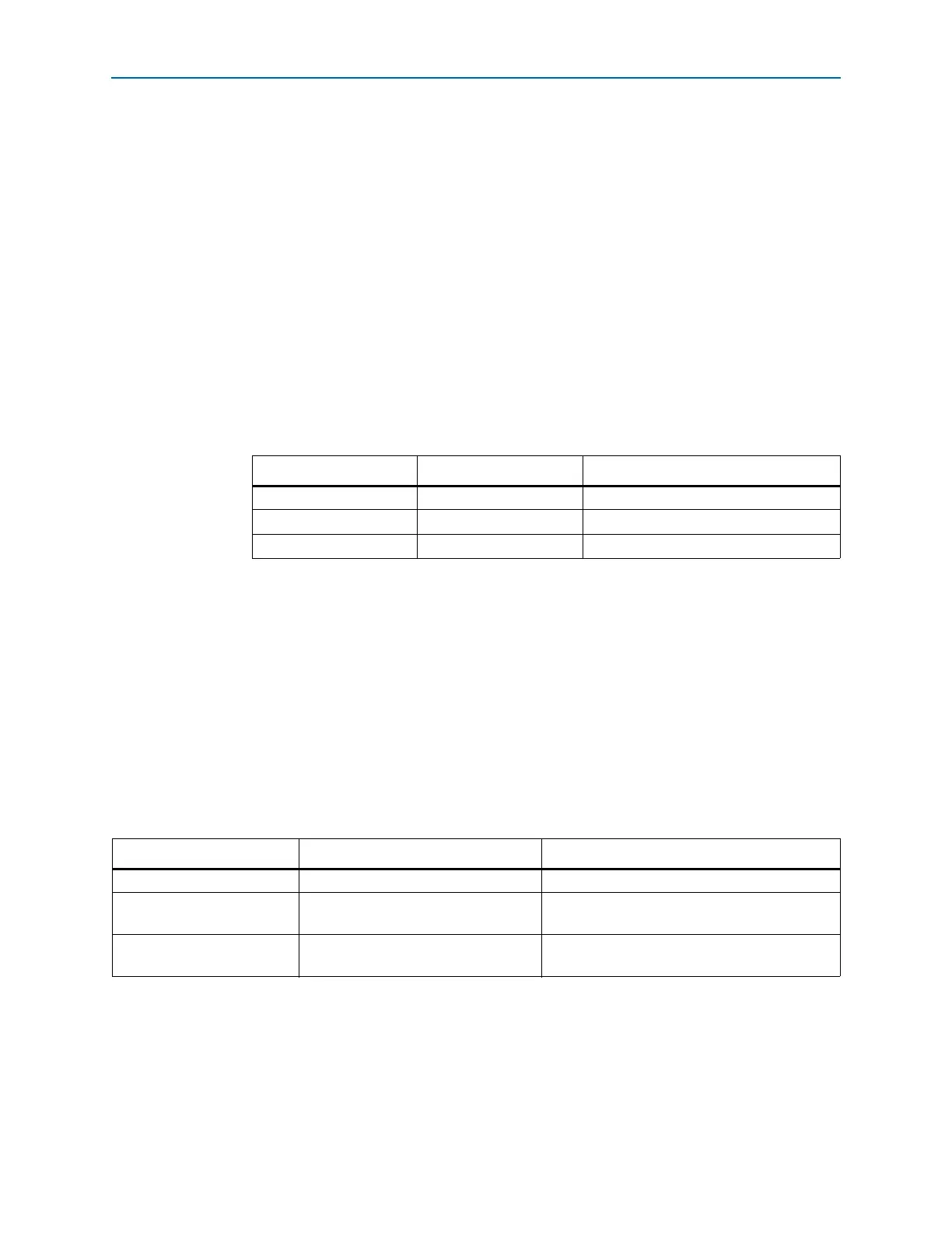
Table 2–4 lists the lock-to-reference (LTR) and lock-to-data (LTD) controller lock
modes for the
rx_locktorefclk
and
rx_locktodata
signals.
Bonded Channel Configuration
In a bonded channel configuration, you can reset all the bonded channels
simultaneously. Examples of bonded channel configurations are the XAUI, PCIe Gen1
×2 and ×4, and Basic ×2 and ×4 functional modes. In Basic ×2 and ×4 functional mode,
you can bond Transmitter Only channels together.
In XAUI mode, the receiver and transmitter channels are bonded. Each of the receiver
channels in this mode has its own
rx_freqlocked
output status signals. You must
consider the timing of these signals in the reset sequence.
Table 2–5 lists the reset and power-down sequences for bonded configurations under
the stated functional modes.
Table 2–4. Lock-To-Reference and Lock-To-Data Modes
rx_locktorefclk rx_locktodata LTR/LTD Controller Lock Mode
1 0 Manual, LTR Mode
— 1 Manual, LTD Mode
0 0 Automatic Lock Mode
Table 2–5. Reset and Power-Down Sequences for Bonded Channel Configurations
Channel Set Up Receiver CDR Mode Refer to
Transmitter Only Basic ×2 and ×4 “Transmitter Only Channel” on page 2–7
Receiver and Transmitter
Automatic lock mode for XAUI
functional mode
“Receiver and Transmitter Channel—Receiver
CDR in Automatic Lock Mode” on page 2–8
Receiver and Transmitter
Manual lock mode for XAUI functional
mode
“Receiver and Transmitter Channel—Receiver
CDR in Manual Lock Mode” on page 2–9