8–36 Chapter 8: Configuration and Remote System Upgrades in Cyclone IV Devices
Configuration
Cyclone IV Device Handbook, May 2013 Altera Corporation
Volume 1
PS Configuration Timing
A PS configuration must meet the setup and hold timing parameters and the
maximum clock frequency. When using a microprocessor or another intelligent host
to control the PS interface, ensure that you meet these timing requirements.
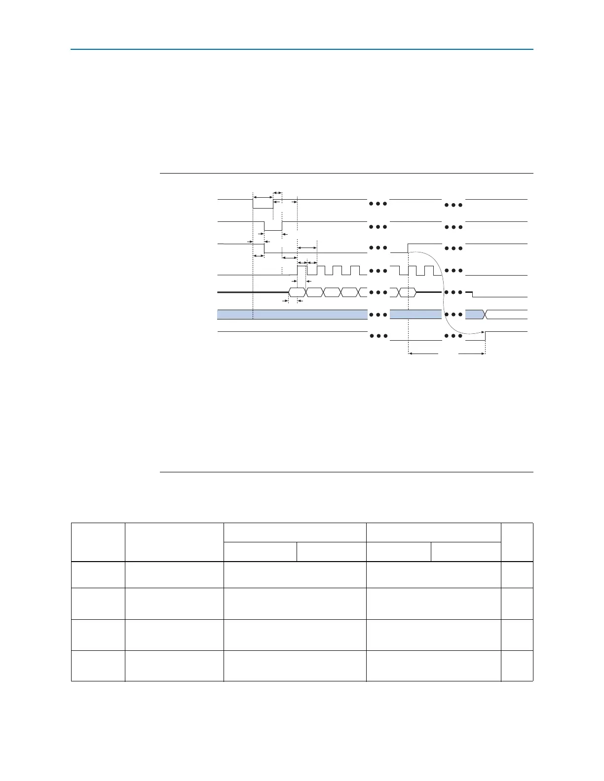
Figure 8–16 shows the timing waveform for PS configuration when using an external
host device.
Tab le 8 –1 2 lists the PS configuration timing parameters for Cyclone IV devices.
Figure 8–16. PS Configuration Timing Waveform
(1)
Notes to Figure 8–16:
(1) The beginning of this waveform shows the device in user mode. In user mode,
nCONFIG
,
nSTATUS
, and
CONF_DONE
are at logic-high levels. When
nCONFIG
is pulled low, a reconfiguration cycle begins.
(2) After power up, the Cyclone IV device holds
nSTATUS
low during POR delay.
(3) After power up, before and during configuration,
CONF_DONE
is low.
(4) In user mode, drive
DCLK
either high or low when using the PS configuration scheme, whichever is more convenient.
When using the AS configuration scheme,
DCLK
is a Cyclone IV device output pin and must not be driven externally.
(5) Do not leave the
DATA[0]
pin floating after configuration. Drive the
DATA[0]
pin high or low, whichever is more
convenient.
nCONFIG
nSTATUS (2)
CONF_DONE (3)
DCLK (4)
DATA[0]
User I/O
INIT_DONE
Bit 0 Bit 1
Bit 2
Bit 3
Bit n
t
CD2UM
t
CF2ST1
t
CF2CD
t
CFG
t
CH
t
CL
t
DH
t
DSU
t
CF2CK
t
STATUS
t
CLK
t
CF2ST0
t
ST2CK
User Mode
(5)
Tri-stated with internal pull-up resistorUser mode
Table 8–12. PS Configuration Timing Parameters For Cyclone IV Devices (Part 1 of 2)
Symbol Parameter
Minimum Maximum
Unit
Cyclone IV
(1)
Cyclone IV E
(2)
Cyclone IV
(1)
Cyclone IV E
(2)
t
CF2CD
nCONFIG
low to
CONF_DONE
low
—500ns
t
CF2ST0
nCONFIG
low to
nSTATUS
low
—500ns
t
CFG
nCONFIG
low pulse
width
500 — ns
t
STATUS
nSTATUS
low pulse
width
45 230
(3)
µs