Chapter 1: Cyclone IV Transceivers Architecture 1–15
Receiver Channel Datapath
February 2015 Altera Corporation Cyclone IV Device Handbook,
Volume 2
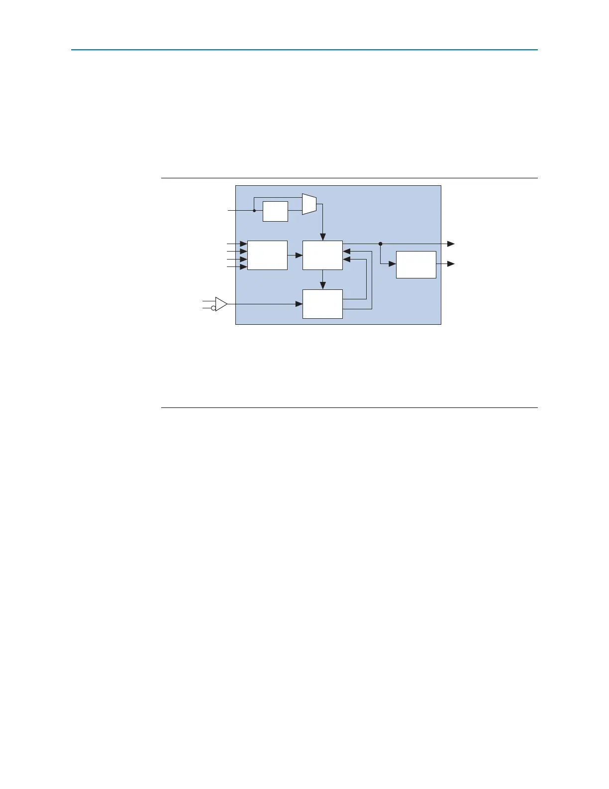
Clock Data Recovery
Each receiver channel has an independent CDR unit to recover the clock from the
incoming serial data stream. The high-speed recovered clock is used to clock the
deserializer for serial-to-parallel conversion of the received input data, and low-speed
recovered clock to clock the receiver PCS blocks. Figure 1–15 illustrates the CDR unit
block diagram.
Each CDR unit gets the reference clock from one of the two multipurpose
phase-locked loops (PLLs) adjacent to the transceiver block. The CDR works by
tracking the incoming data with a phase detector and finding the optimum sampling
clock phase from the phase interpolator unit. The CDR operations are controlled by
the LTR/LTD controller block, where the CDR may operate in the following states:
■ Lock-to-reference (LTR) state—phase detector disabled and CDR ignores incoming
data
■ Lock-to-data (LTD) state—phase detector enabled and CDR tracks incoming data
to find the optimum sampling clock phase
State transitions are supported with automatic lock mode and manual lock mode.
Automatic Lock Mode
Upon receiver power-up and reset cycle, the CDR is put into LTR state. Transition to
the LTD state is performed automatically when both of the following conditions are
met:
■ Signal detection circuitry indicates the presence of valid signal levels at the
receiver input buffer. This condition is valid for PCI Express (PIPE) mode only.
CDR transitions are not dependent on signal detection circuitry in other modes.
■ The recovered clock is within the configured part per million (ppm) frequency
threshold setting with respect to the CDR clocks from multipurpose PLL.
Figure 1–15. CDR Unit Block Diagram
Notes to Figure 1–15:
(1) Optional RX local divider for CDR clocks from multipurpose PLL is only available in each CDR unit for EP4CGX30
(F484 package), EP4CGX50, and EP4CGX75 devices. This block is used with the transceiver dynamic reconfiguration
feature. For more information, refer to the Cyclone IV Dynamic Reconfiguration chapter and AN 609: Implementing
Dynamic Reconfiguration in Cyclone IV GX Devices.
(2) CDR state transition in automatic lock mode is not dependent on
rx_signaldetect
signal, except when configured
in PCI Express (PIPE) mode only.
rx_datain
rx_freqlocked
Up
Down
rx_signaldetect(3)
Low-speed recovered
clock (for receiver PCS)
High-speed recovered
clock (for deserializer)
CDR clocks
from MPLL
Sampling
Clocks
rx_locktorefclk
rx_locktodata
LTR/LTD
Controller
Phase
Detector
Clock
Divider
Phase
Interpolator
/2
(2)