8–52 Chapter 8: Configuration and Remote System Upgrades in Cyclone IV Devices
Configuration
Cyclone IV Device Handbook, May 2013 Altera Corporation
Volume 1
1 JTAG configuration allows an unlimited number of Cyclone IV devices to be cascaded
in a JTAG chain.
f For more information about configuring multiple Altera devices in the same
configuration chain, refer to the Configuring Mixed Altera FPGA Chains chapter in
volume 2 of the Configuration Handbook.
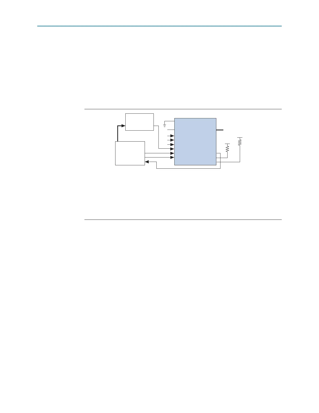
Figure 8–27 shows JTAG configuration with a Cyclone IV device and a
microprocessor.
Configuring Cyclone IV Devices with Jam STAPL
Jam
™
STAPL, JEDEC standard JESD-71, is a standard file format for in-system
programmability (ISP) purposes. Jam STAPL supports programming or configuration
of programmable devices and testing of electronic systems, using the IEEE 1149.1
JTAG interface. Jam STAPL is a freely licensed open standard. The Jam Player
provides an interface for manipulating the IEEE Std. 1149.1 JTAG TAP state machine.
f For more information about JTAG and Jam STAPL in embedded environments, refer
to AN 425: Using Command-Line Jam STAPL Solution for Device Programming. To
download the Jam Player, visit the Altera website (www.altera.com).
Configuring Cyclone IV Devices with the JRunner Software Driver
The JRunner software driver allows you to configure Cyclone IV devices through the
ByteBlaster II or ByteBlasterMV cables in JTAG mode. The supported programming
input file is in .rbf format. The JRunner software driver also requires a Chain
Description File (.cdf) generated by the Quartus II software. The JRunner software
driver is targeted for embedded JTAG configuration. The source code is developed for
the Windows NT operating system (OS). You can customize the code to make it run
on your embedded platform.
Figure 8–27. JTAG Configuration of a Single Device Using a Microprocessor
Notes to Figure 8–27:
(1) You must connect the pull-up resistor to a supply that provides an acceptable input signal for all devices in the chain.
(2) Connect the
nCONFIG
and
MSEL
pins to support a non-JTAG configuration scheme. If you only use a JTAG
configuration, connect the
nCONFIG
pin to logic-high and the
MSEL
pins to GND. In addition, pull
DCLK
and
DATA[0]
to either high or low, whichever is convenient on your board.
(3) You must connect the
nCE
pin to GND or driven low for successful JTAG configuration.
(4) All I/O inputs must maintain a maximum AC voltage of 4.1 V. Signals driving into
TDI
,
TMS
, and
TCK
must fit the
maximum overshoot outlined in Equation 8–1 on page 8–5.
nCONFIG
DATA[0]
DCLK
TDI
(4)
TCK (4)
TMS (4)
Microprocessor
Memory
ADDR
TDO
Cyclone IV Device
nSTATUS
CONF_DONE
V
CCIO
V
CCIO
10 kΩ
10 kΩ
(2)
(2)
N.C.
(2)
(2)
(1)
(1)
(3)
MSEL[ ]
nCE
nCEO
DATA