5–30 Chapter 5: Clock Networks and PLLs in Cyclone IV Devices
Hardware Features
Cyclone IV Device Handbook, October 2012 Altera Corporation
Volume 1
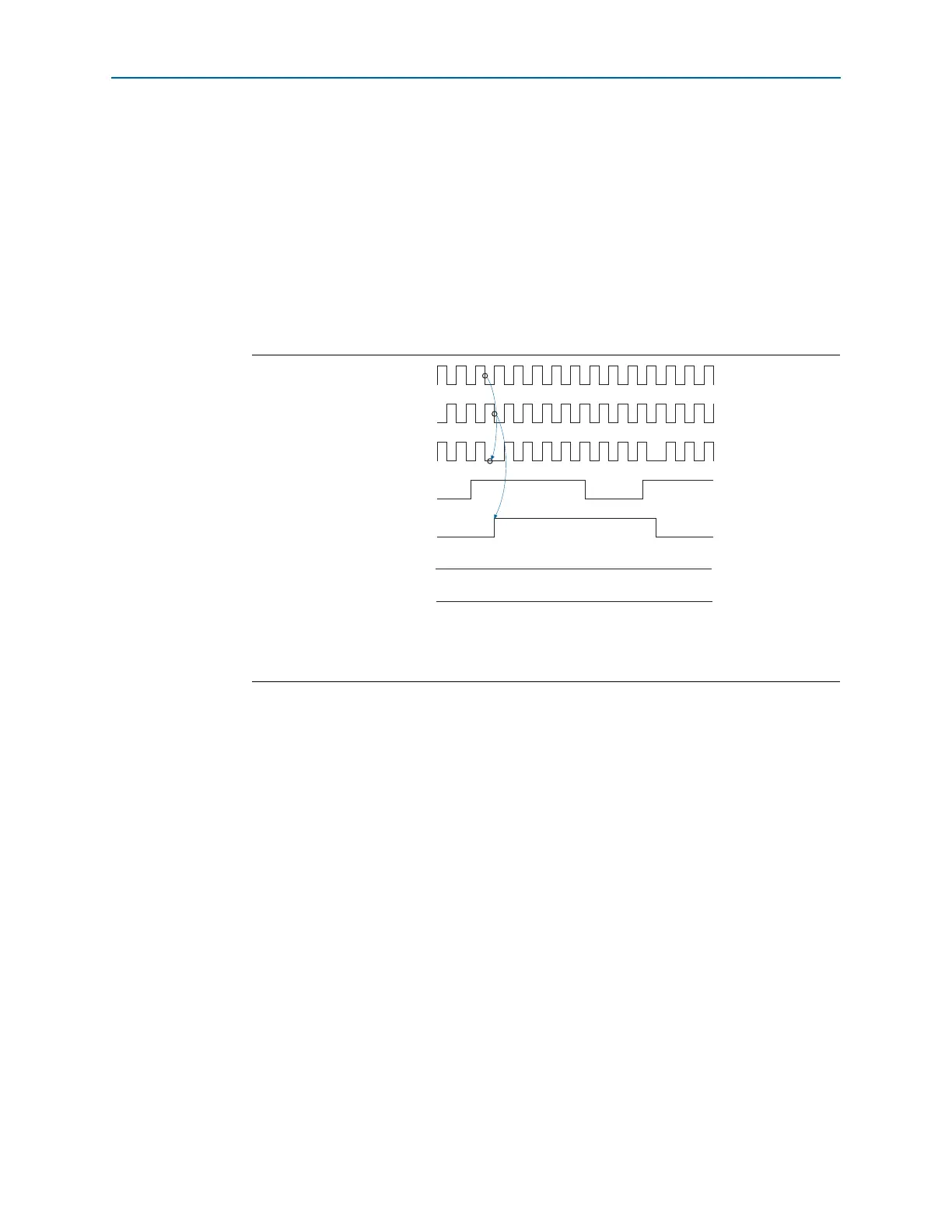
In this mode, the
activeclock
signal mirrors the
clkswitch
signal. As both blocks are
still functional during the manual switch, neither
clkbad
signals go high. Because the
switchover circuit is positive edge-sensitive, the falling edge of the
clkswitch
signal
does not cause the circuit to switch back from
inclk1
to
inclk0
. When the
clkswitch
signal goes high again, the process repeats. The
clkswitch
signal and the automatic
switch only works depending on the availability of the clock that is switched to. If the
clock is unavailable, the state machine waits until the clock is available.
1 When CLKSWITCH = 1, it overrides the automatic switch-over function. As long as
clkswitch
signal is high, further switch-over action is blocked.
Manual Clock Switchover
PLLs of Cyclone IV devices support manual switchover, in which the
clkswitch
signal controls whether
inclk0
or
inclk1
is the input clock to the PLL. The
characteristics of a manual switchover are similar to the manual override feature in an
automatic clock switchover, in which the switchover circuit is edge-sensitive. When
the
clkswitch
signal goes high, the switchover sequence starts. The falling edge of the
clkswitch
signal does not cause the circuit to switch back to the previous input clock.
f For more information about PLL software support in the Quartus II software, refer to
the ALTPLL Megafunction User Guide.
Guidelines
Use the following guidelines to design with clock switchover in PLLs:
■ Clock loss detection and automatic clock switchover require the
inclk0
and
inclk1
frequencies be within 20% of each other. Failing to meet this requirement
causes the
clkbad0
and
clkbad1
signals to function improperly.
Figure 5–19. Clock Switchover Using the clkswitch Control
(1)
Note to Figure 5–19:
(1) Both
inclk0
and
inclk1
must be running when the
clkswitch
signal goes high to start a manual clock switchover
event.
inclk0
inclk1
muxout
clkswitch
activeclock
clkbad0
clkbad1