1–76 Chapter 1: Cyclone IV Transceivers Architecture
Transceiver Functional Modes
Cyclone IV Device Handbook, February 2015 Altera Corporation
Volume 2
Receive Bit-Slip Indication
The number of bits slipped in the word aligner for synchronization in manual
alignment mode is provided with the
rx_bitslipboundaryselectout[4..0]
signal.
For example, if one bit is slipped in word aligner to achieve synchronization, the
output on
rx_bitslipboundaryselectout[4..0]
signal shows a value of 1 (5'00001).
The information from this signal helps in latency calculation through the receiver as
the number of bits slipped in the word aligner varies at each synchronization.
Transmit Bit-Slip Control
The transmitter datapath supports bit-slip control to delay the serial data
transmission by a number of specified bits in PCS with
tx_bitslipboundaryselect[4..0]
port. With 8- or 10-bit channel width, the
transmitter supports zero to nine bits of data slip. This feature helps to maintain a
fixed round trip latency by compensating latency variation from word aligner when
providing the appropriate values on t
x_bitslipboundaryselect[4..0]
port based on
values on
rx_bitslipboundaryselectout[4..0]
signal.
PLL PFD feedback
In Deterministic Latency mode, when transmitter input reference clock frequency is
the same as the low-speed clock, the PLL that clocks the transceiver supports PFD
feedback. When enabled, the PLL compensates for delay uncertainty in the low-speed
clock (
tx_clkout
in ×1 configuration or
coreclkout
in ×4 configuration) path relative
to input reference and the transmitter datapath latency is fixed relative to the
transmitter input reference clock.
SDI Mode
SDI mode provides the non-bonded (×1) transceiver channel datapath configuration
for HD- and 3G-SDI protocol implementations.
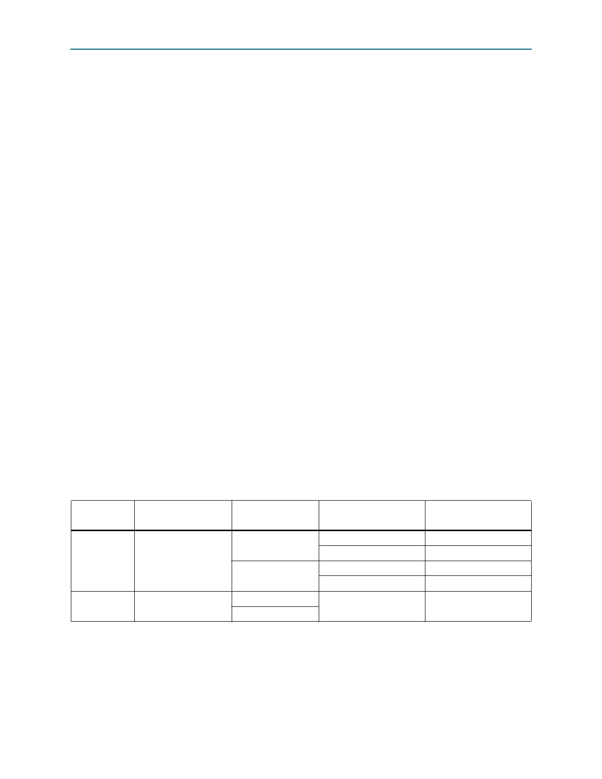
Cyclone IV GX transceivers configured in SDI mode provides the serialization and
deserialization functions that supports the SDI data rates as listed in Table 1–24.
1 SDI functions such as scrambling/de-scrambling, framing, and cyclic redundancy
check (CRC) must be implemented in the user logic.
Table 1–24. Supported SDI Data Rates
SMPTE
Standard
(1)
Configuration Data Rate (Mbps)
FPGA Fabric-to-
Transceiver Width
Byte SERDES Usage
292M High definition (HD)
1483.5
20-bit Used
10-bit Not used
1485
20-bit Used
10-bit Not used
424M Third-generation (3G)
2967
20-bit Used
2970
Note to Table 1–24:
(1) Society of Motion Picture and Television Engineers (SMPTE).