1–4 Chapter 1: Cyclone IV Transceivers Architecture
Architectural Overview
Cyclone IV Device Handbook, February 2015 Altera Corporation
Volume 2
Architectural Overview
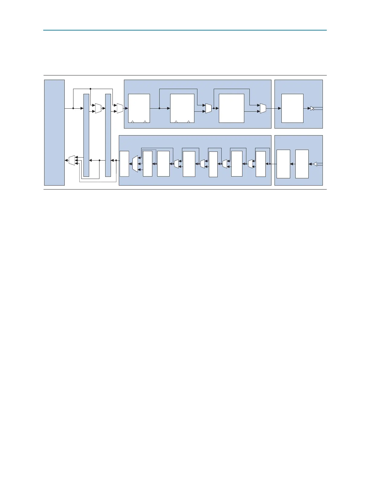
Figure 1–3 shows the Cyclone IV GX transceiver channel datapath.
Each transceiver channel consists of a transmitter and a receiver datapath. Each
datapath is further structured into the following:
■ Physical media attachment (PMA)—includes analog circuitry for I/O buffers,
clock data recovery (CDR), serializer/deserializer (SERDES), and programmable
pre-emphasis and equalization to optimize serial data channel performance.
■ Physical coding sublayer (PCS)—includes hard logic implementation of digital
functionality within the transceiver that is compliant with supported protocols.
Outbound parallel data from the FPGA fabric flows through the transmitter PCS and
PMA, is transmitted as serial data. Received inbound serial data flows through the
receiver PMA and PCS into the FPGA fabric. The transceiver supports the following
interface widths:
■ FPGA fabric-transceiver PCS—8, 10, 16, or 20 bits
■ PMA-PCS—8 or 10 bits
f The transceiver channel interfaces through the PIPE when configured for PCIe
protocol implementation. The PIPE is compliant with version 2.00 of the PHY Interface
for the PCI Express Architecture specification.
Figure 1–3. Transceiver Channel Datapath for Cyclone IV GX Devices
Byte Serializer
8B/10B Encoder
Receiver Channel PCS Receiver Channel PMA
Transmitter Channel PCS Transmitter Channel PMA
Serializer
PCIe Hard IP
FPGA
Fabric
PIPE Interface
Tx Phase
Comp
FIFO
tx_datain
rx_dataout
tx_dataout
rx_datain
wr_clk rd_clk
Deserial-
izer
CDR
wr_clk rd_clk
Byte
De-
serializer
Byte
Order-
ing
Deskew
FIFO
8B/10B
Decoder
Rate
Match
FIFO
Word
Aligner
Rx
Phase
Comp
FIFO