Chapter 8: Configuration and Remote System Upgrades in Cyclone IV Devices 8–37
Configuration
May 2013 Altera Corporation Cyclone IV Device Handbook,
Volume 1
PS Configuration Using a Download Cable
In this section, the generic term “download cable” includes the Altera USB-Blaster
USB port download cable, MasterBlaster™ serial and USB communications cable,
ByteBlaster II parallel port download cable, the ByteBlasterMV
™
parallel port
download cable, and the EthernetBlaster communications cable.
In the PS configuration with a download cable, an intelligent host (such as a PC)
transfers data from a storage device to the Cyclone IV device through the download
cable.
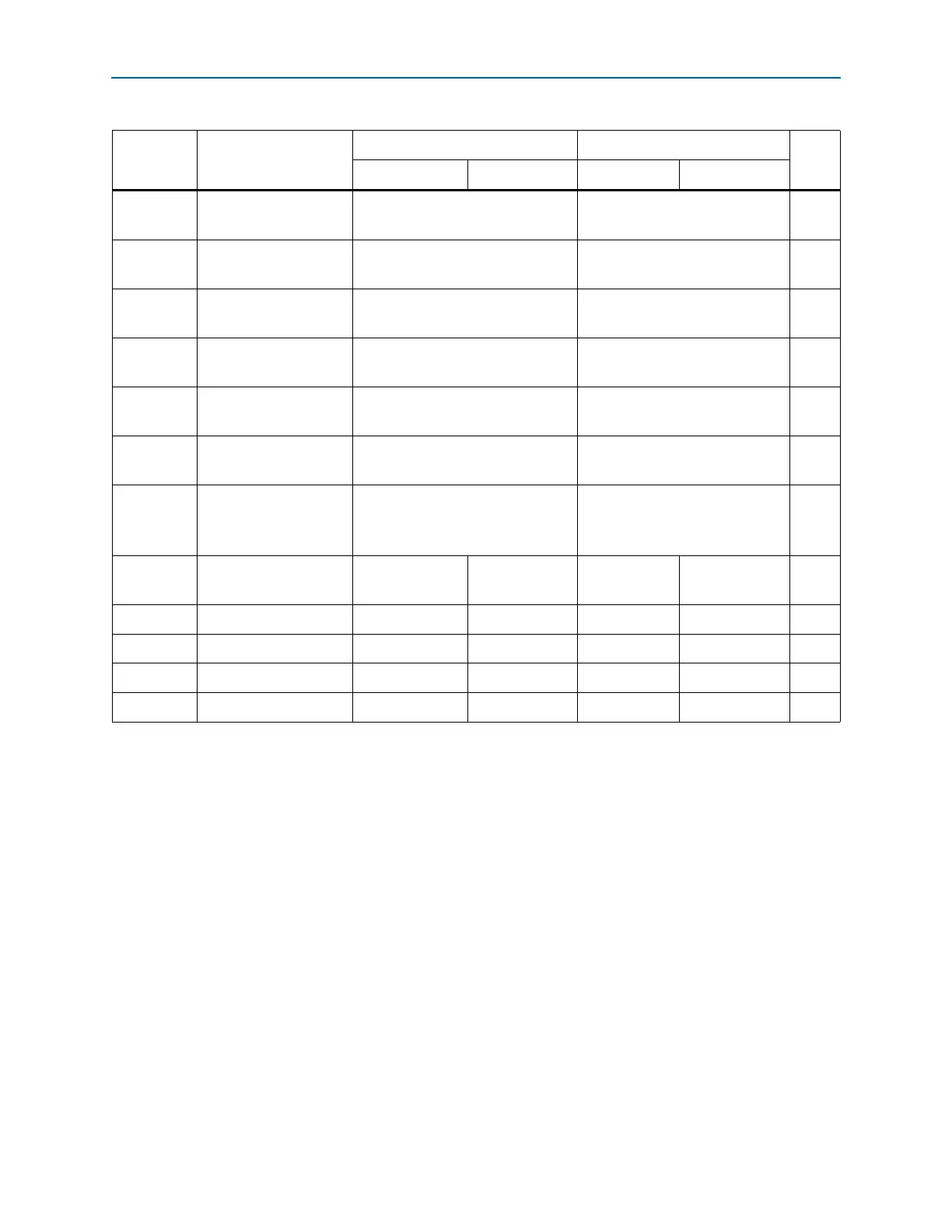
t
CF2ST1
nCONFIG
high to
nSTATUS
high
— 230
(4)
µs
t
CF2CK
nCONFIG
high to first
rising edge on DCLK
230
(3)
—µs
t
ST2CK
nSTATUS
high to first
rising edge of
DCLK
2—µs
t
DH
Data hold time after
rising edge on
DCLK
0—ns
t
CD2UM
CONF_DONE
high to
user mode
(5)
300 650 µs
t
CD2CU
CONF_DONE
high to
CLKUSR
enabled
4 × maximum
DCLK
period — —
t
CD2UMC
CONF_DONE
high to
user mode with
CLKUSR option on
t
CD2CU
+ (3,192 × CLKUSR period)
——
t
DSU
Data setup time before
rising edge on
DCLK
58——ns
t
CH
DCLK
high time 3.2 6.4 — — ns
t
CL
DCLK
low time 3.2 6.4 — — ns
t
CLK
DCLK
period 7.5 15 — — ns
f
MAX
DCLK
frequency
(6)
— — 133 66 MHz
Notes to Table 8–12:
(1) Applicable for Cyclone IV GX and Cyclone IV E devices with 1.2-V core voltage.
(2) Applicable for Cyclone IV E devices with 1.0-V core voltage.
(3) This value is applicable if you do not delay configuration by extending the nCONFIG or nSTATUS low pulse width.
(4) This value is applicable if you do not delay configuration by externally holding the
nSTATUS
low.
(5) The minimum and maximum numbers apply only if you choose the internal oscillator as the clock source for starting the device.
(6) Cyclone IV E devices with 1.0-V core voltage have slower F
MAX
when compared with Cyclone IV GX devices with 1.2-V core voltage.
Table 8–12. PS Configuration Timing Parameters For Cyclone IV Devices (Part 2 of 2)
Symbol Parameter
Minimum Maximum
Unit
Cyclone IV
(1)
Cyclone IV E
(2)
Cyclone IV
(1)
Cyclone IV E
(2)