6–10 Chapter 6: I/O Features in Cyclone IV Devices
OCT Support
Cyclone IV Device Handbook, March 2016 Altera Corporation
Volume 1
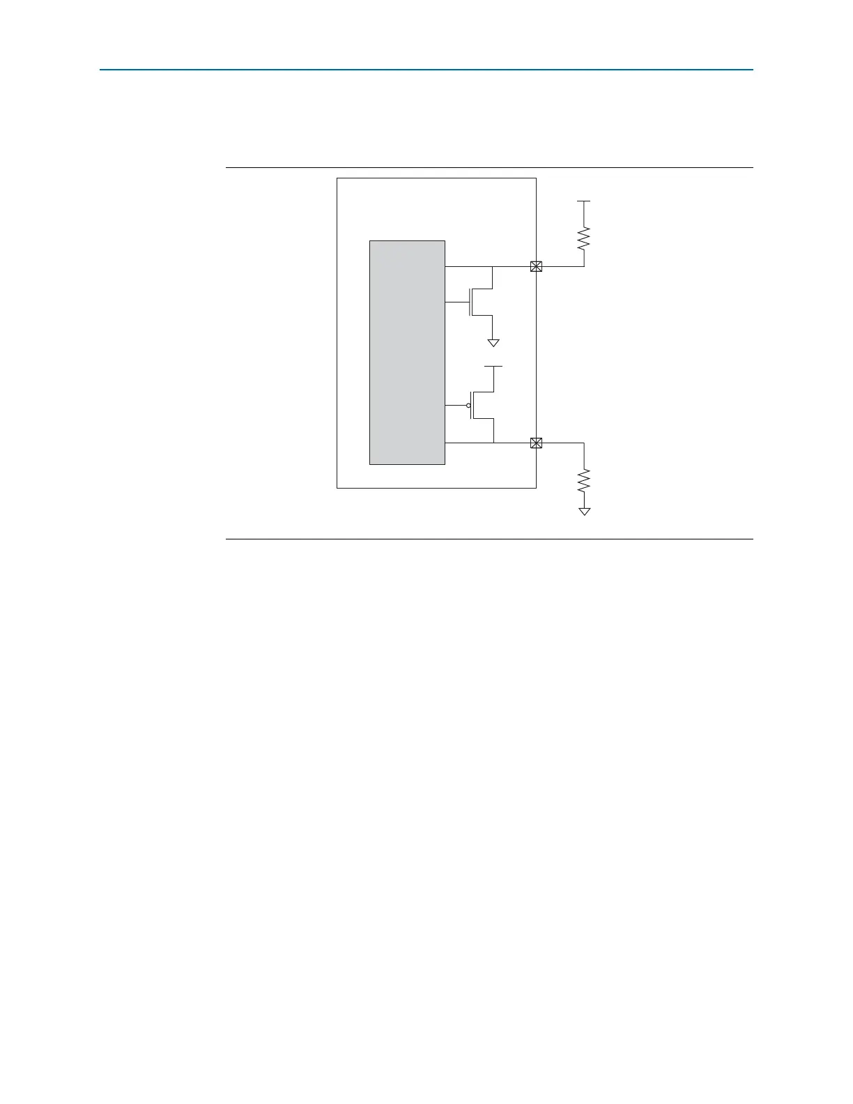
Figure 6–3 shows the external calibration resistors setup on the
RUP
and
RDN
pins and
the associated OCT calibration circuitry.
RUP
and
RDN
pins go to a tri-state condition when calibration is completed or not
running. These two pins are dual-purpose I/Os and function as regular I/Os if you
do not use the calibration circuit.
On-Chip Series Termination Without Calibration
Cyclone IV devices support driver impedance matching to match the impedance of
the transmission line, which is typically 25 or 50 . When used with the output
drivers, OCT sets the output driver impedance to 25 or 50 . Cyclone IV devices also
support I/O driver series termination (R
S
=50) for SSTL-2 and SSTL-18.
Figure 6–3. Cyclone IV Devices R
S
OCT with Calibration Setup
Cyclone IV Device Family OCT with
Calibration with RUP and RDN pins
OCT
Calibration
Circuitry
V
CCIO
V
CCIO
RUP
RDN
External
Calibration
Resistor
External
Calibration
Resistor
GND