Chapter 3: Memory Blocks in Cyclone IV Devices 3–9
Memory Modes
November 2011 Altera Corporation Cyclone IV Device Handbook,
Volume 1
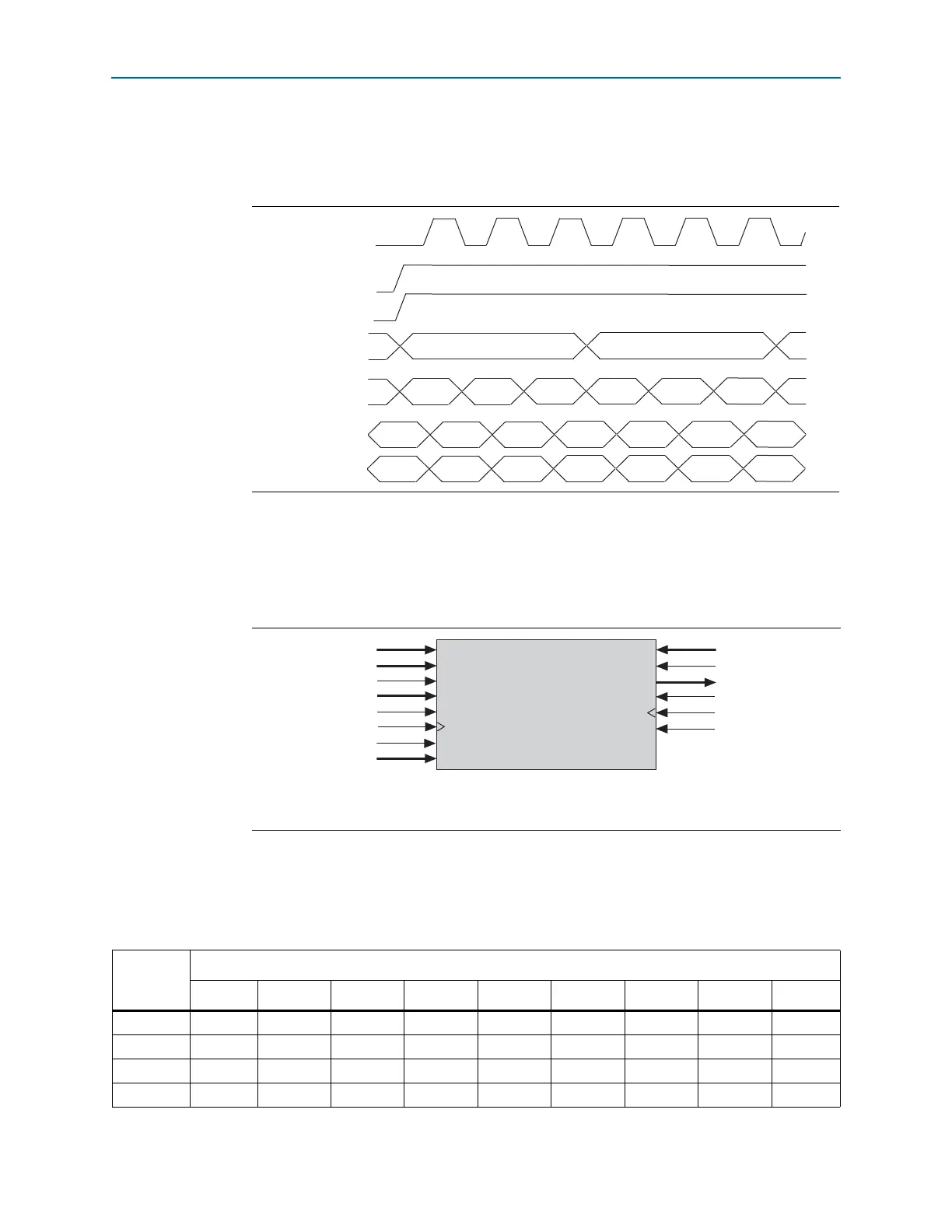
Figure 3–7 shows a timing waveform for read and write operations in single-port
mode with unregistered outputs. Registering the outputs of the RAM simply delays
the
q
output by one clock cycle.
Simple Dual-Port Mode
Simple dual-port mode supports simultaneous read and write operations to different
locations. Figure 3–8 shows the simple dual-port memory configuration.
Cyclone IV devices M9K memory blocks support mixed-width configurations,
allowing different read and write port widths. Table 3–3 lists mixed-width
configurations.
Figure 3–7. Cyclone IV Devices Single-Port Mode Timing Waveform
clk_a
wren_a
address_a
data_a
rden_a
q_a (old data)
a0 a1
ABC D EF
a0(old data) a1(old data)
AB D E
q_a (new data)
ADBC E F
Figure 3–8. Cyclone IV Devices Simple Dual-Port Memory
(1)
Note to Figure 3–8:
(1) Simple dual-port RAM supports input or output clock mode in addition to the read or write clock mode shown.
data[ ]
wraddress[ ]
wren
byteena[]
wr_addressstall
wrclock
wrclocken
aclr
rdaddress[ ]
rden
q[ ]
rd_addressstall
rdclock
rdclocken
Table 3–3. Cyclone IV Devices M9K Block Mixed-Width Configurations (Simple Dual-Port Mode) (Part 1 of 2)
Read Port
Write Port
8192
× 14096× 2 2048 × 4 1024 × 8 512 × 16 256 × 32 1024 × 9512× 18 256 × 36
8192 × 1 vvvvvv———
4096 × 2 vvvvvv———
2048 × 4 vvvvvv———
1024 × 8 vvvvvv———