2–10 Chapter 2: Cyclone IV Reset Control and Power Down
Transceiver Reset Sequences
Cyclone IV Device Handbook, September 2014 Altera Corporation
Volume 2
As shown in Figure 2–5, perform the following reset procedure for the receiver CDR
in manual lock mode configuration:
1. After power up, assert
pll_areset
for a minimum period of 1 s (the time
between markers 1 and 2).
2. Keep the
tx_digitalreset
,
rx_analogreset
,
rx_digitalreset
, and
rx_locktorefclk
signals asserted and the
rx_locktodata
signal deasserted during
this time period. After you deassert the
pll_areset
signal, the multipurpose PLL
starts locking to the input reference clock.
3. After the multipurpose PLL locks, as indicated by the
pll_locked
signal going
high (marker 3), deassert the
tx_digitalreset
signal (marker 4). For the receiver
operation, after deassertion of the
busy
signal, wait for two parallel clock cycles to
deassert the
rx_analogreset
signal.
4. In a bonded channel group, wait for at least t
LTR_LTD_Manual
, then deassert
rx_locktorefclk
and assert
rx_locktodata
(marker 7). At this point, the receiver
CDR of all the channels enters into lock-to-data mode and starts locking to the
received data.
5. After asserting the
rx_locktodata
signal, wait for at least t
LTD_Manual
before
deasserting
rx_digitalreset
(the time between markers 7 and 8). At this point,
the transmitter and receiver are ready for data traffic.
Non-Bonded Channel Configuration
In non-bonded channels, each channel in the ALTGX MegaWizard Plug-In Manager
instance contains its own
tx_digitalreset
,
rx_analogreset
,
rx_digitalreset
, and
rx_freqlocked
signals.
You can reset each channel independently. For example, if there are four non-bonded
channels, the ALTGX MegaWizard Plug-In Manager provides four each of the
following signals:
tx_digitalreset
,
rx_analogreset
,
rx_digitalreset
, and
rx_freqlocked
.
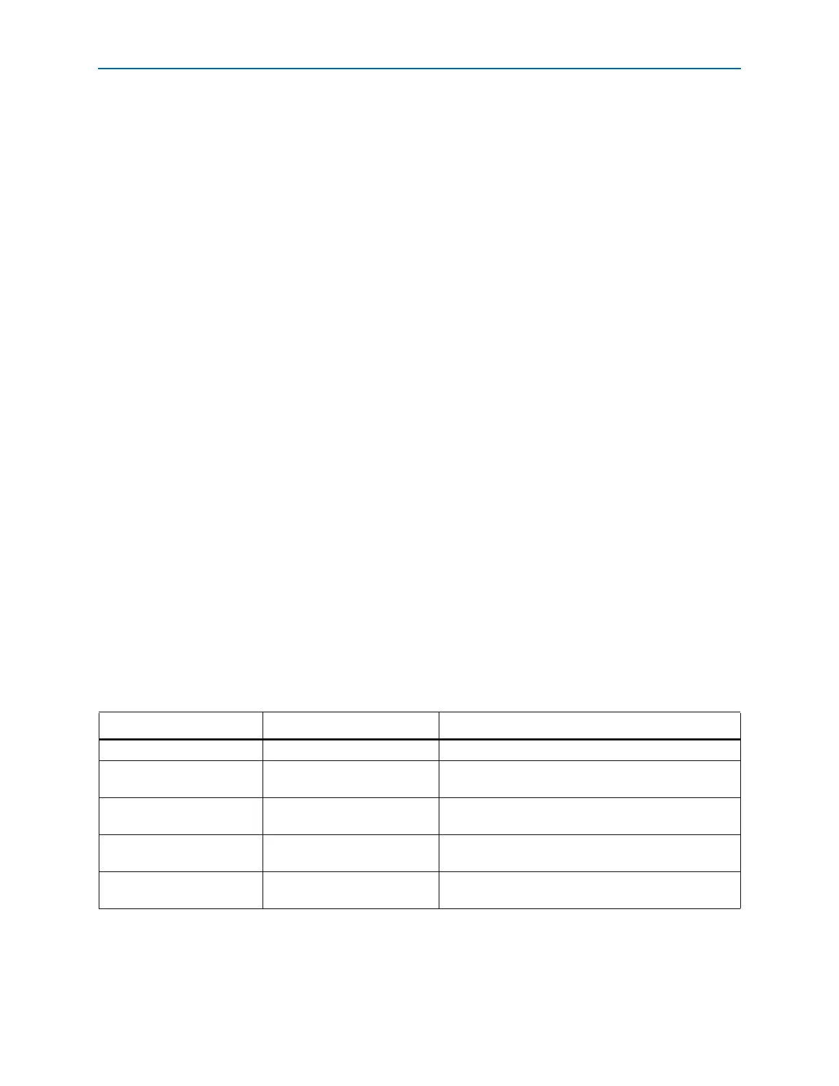
Table 2–6 lists the reset and power-down sequences for one channel in a non-bonded
configuration under the stated functional modes.
1 Follow the same reset sequence for all the other channels in the non-bonded
configuration.
Table 2–6. Reset and Power-Down Sequences for Non-Bonded Channel Configurations
Channel Set Up Receiver CDR Mode Refer to
Transmitter Only Basic ×1 “Transmitter Only Channel” on page 2–11
Receiver Only Automatic lock mode
“Receiver Only Channel—Receiver CDR in Automatic
Lock Mode” on page 2–11
Receiver Only Manual lock mode
“Receiver Only Channel—Receiver CDR in Manual Lock
Mode” on page 2–12
Receiver and Transmitter Automatic lock mode
“Receiver and Transmitter Channel—Receiver CDR in
Automatic Lock Mode” on page 2–13
Receiver and Transmitter Manual lock mode
“Receiver and Transmitter Channel—Receiver CDR in
Manual Lock Mode” on page 2–14