8–44 Chapter 8: Configuration and Remote System Upgrades in Cyclone IV Devices
Configuration
Cyclone IV Device Handbook, May 2013 Altera Corporation
Volume 1
FPP Configuration Timing
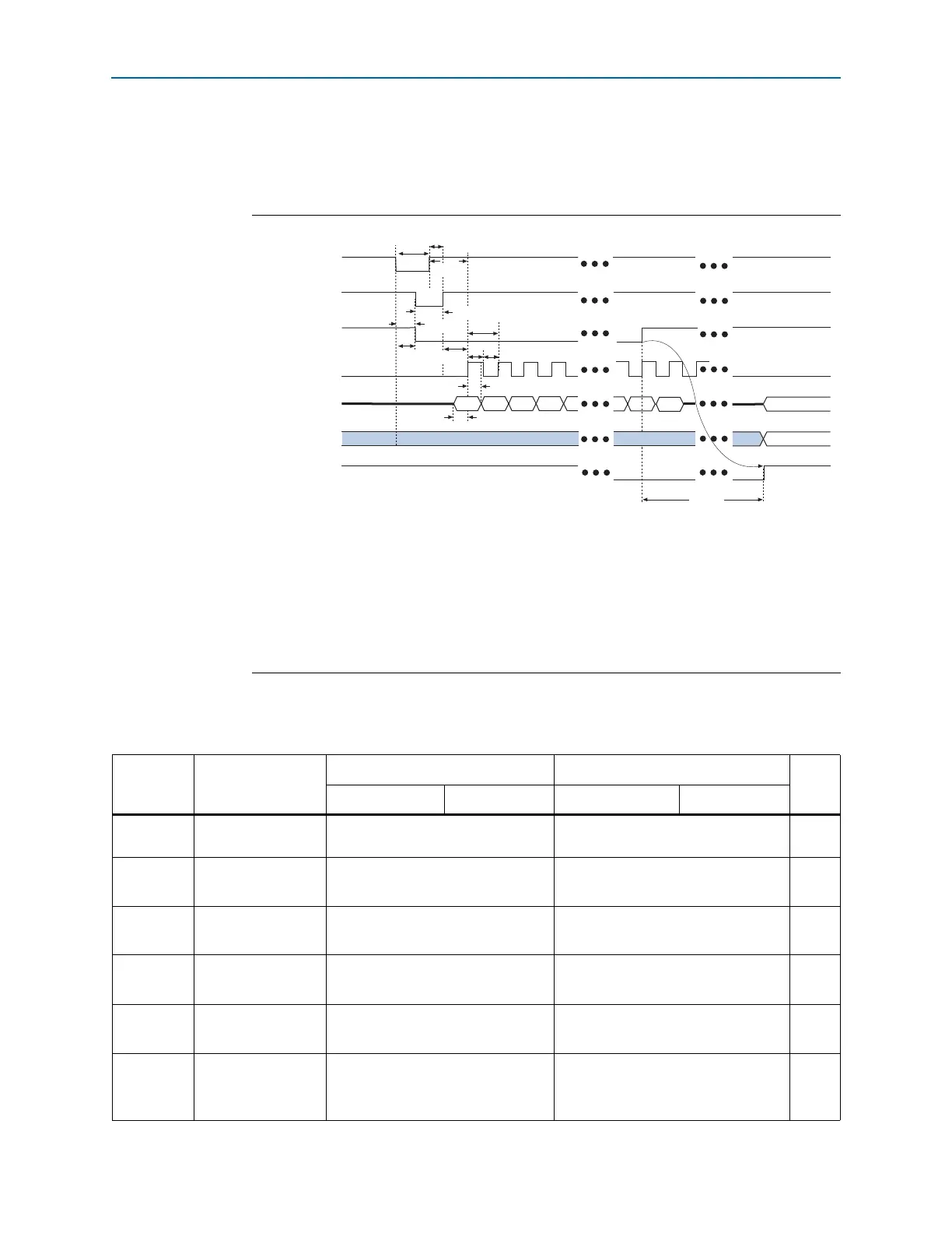
Figure 8–22 shows the timing waveform for the FPP configuration when using an
external host.
Tab le 8 –1 3 lists the FPP configuration timing parameters for Cyclone IV devices.
Figure 8–22. FPP Configuration Timing Waveform
(1)
Notes to Figure 8–22:
(1) The beginning of this waveform shows the device in user mode. In user mode,
nCONFIG
,
nSTATUS
, and
CONF_DONE
are at logic-high levels. When
nCONFIG
is pulled low, a reconfiguration cycle begins.
(2) After power up, the Cyclone IV device holds
nSTATUS
low during POR delay.
(3) After power up, before and during configuration,
CONF_DONE
is low.
(4) Do not leave
DCLK
floating after configuration. It must be driven high or low, whichever is more convenient.
(5)
DATA[7..0]
is available as a user I/O pin after configuration; the state of the pin depends on the dual-purpose pin
settings.
nCONFIG
nSTATUS (2)
CONF_DONE (3)
DCLK
DATA[7..0]
User I/O
INIT_DONE
Byte 0 Byte 1
Byte 2
Byte 3 Byte n-1
t
CD2UM
t
CF2ST1
t
CF2CD
t
CFG
t
CH
t
CL
t
DH
t
DSU
t
CF2CK
t
STATUS
t
CLK
t
CF2ST0
t
ST2CK
User Mode
(5)
Tri-stated with internal pull-up resistor
(4)
User Mode
Byte n
User mode
Table 8–13. FPP Timing Parameters for Cyclone IV Devices (Part 1 of 2)
Symbol Parameter
Minimum Maximum
Unit
Cyclone IV
(1)
Cyclone IV E
(2)
Cyclone IV
(1)
Cyclone IV E
(2)
t
CF2CD
nCONFIG
low to
CONF_DONE
low
— 500 ns
t
CF2ST0
nCONFIG
low to
nSTATUS
low
— 500 ns
t
CFG
nCONFIG
low pulse
width
500 — ns
t
STATUS
nSTATUS
low pulse
width
45 230
(3)
µs
t
CF2ST1
nCONFIG
high to
nSTATUS
high
— 230
(4)
µs
t
CF2CK
nCONFIG
high to
first rising edge on
DCLK
230
(3)
—µs