Chapter 8: Configuration and Remote System Upgrades in Cyclone IV Devices 8–43
Configuration
May 2013 Altera Corporation Cyclone IV Device Handbook,
Volume 1
DCLK
,
DATA[7..0]
, and
CONF_DONE
) are connected to every device in the chain.
Configuration signals may require buffering to ensure signal integrity and prevent
clock skew problems. Ensure that the
DCLK
and
DATA
lines are buffered. All devices
initialize and enter user mode at the same time, because all device
CONF_DONE
pins are
tied together.
All
nSTATUS
and
CONF_DONE
pins are tied together and if any device detects an error,
configuration stops for the entire chain and the entire chain must be reconfigured. For
example, if the first device flags an error on
nSTATUS
, it resets the chain by pulling its
nSTATUS
pin low. This behavior is similar to a single device detecting an error.
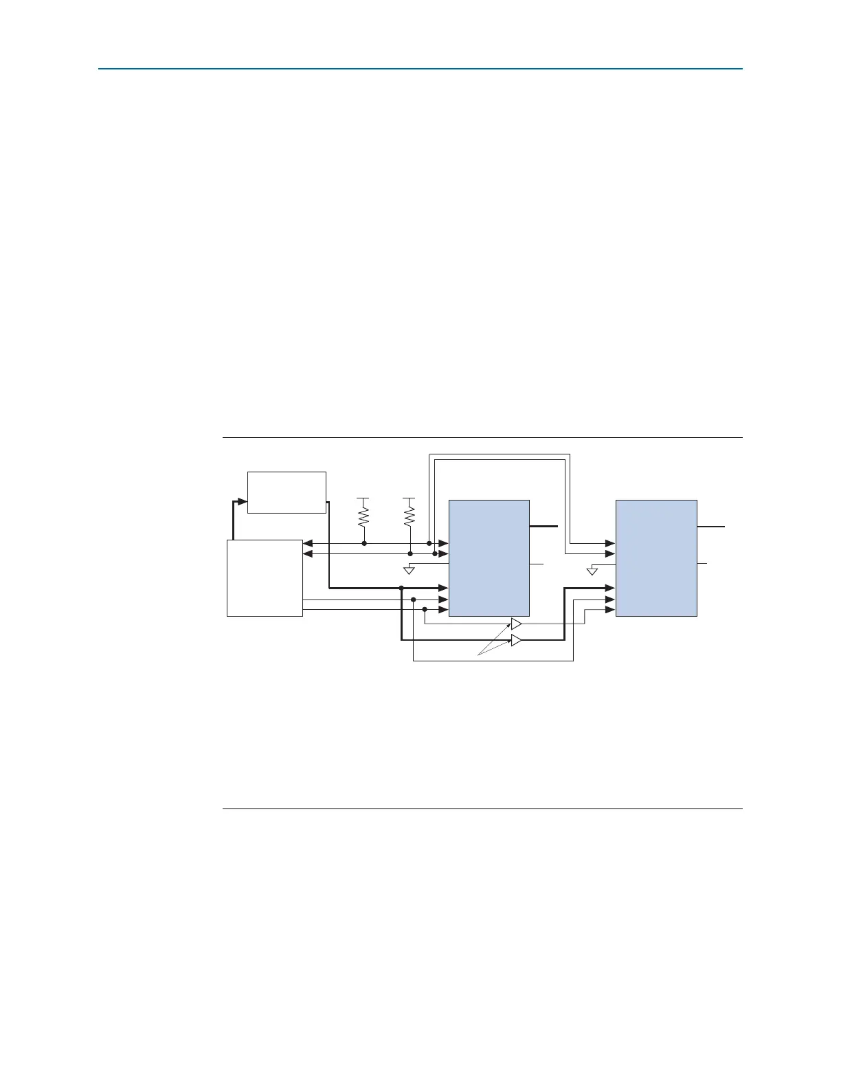
Figure 8–21 shows multi-device FPP configuration when both Cyclone IV devices are
receiving the same configuration data. Configuration pins (
nCONFIG
,
nSTATUS
,
DCLK
,
DATA[7..0]
, and
CONF_DONE
) are connected to every device in the chain. Configuration
signals may require buffering to ensure signal integrity and prevent clock skew
problems. Ensure that the
DCLK
and
DATA
lines are buffered. Devices must be of the
same density and package. All devices start and complete configuration at the same
time.
You can use a single configuration chain to configure Cyclone IV devices with other
Altera devices that support FPP configuration. To ensure that all devices in the chain
complete configuration at the same time or that an error flagged by one device starts
reconfiguration in all devices, tie all the
CONF_DONE
and
nSTATUS
pins together.
f For more information about configuring multiple Altera devices in the same
configuration chain, refer to Configuring Mixed Altera FPGA Chains in volume 2 of the
Configuration Handbook.
Figure 8–21. Multi-Device FPP Configuration Using an External Host When Both Devices Receive
the Same Data
Notes to Figure 8–21:
(1) You must connect the pull-up resistor to a supply that provides an acceptable input signal for all devices in the chain.
V
CC
must be high enough to meet the V
IH
specification of the I/O on the device and the external host.
(2) The
nCEO
pins of both devices are left unconnected or used as user I/O pins when configuring the same configuration
data into multiple devices.
(3) The
MSEL
pin settings vary for different configuration voltage standards and POR time. To connect the
MSEL
pins,
refer to Table 8–4 on page 8–8 and Table 8–5 on page 8–9. Connect the
MSEL
pins directly to V
CCA
or GND.
(4) All I/O inputs must maintain a maximum AC voltage of 4.1 V.
DATA[7..0]
and
DCLK
must fit the maximum overshoot
outlined in Equation 8–1 on page 8–5.
External Host
(MAX II Device or
Microprocessor)
Memory
ADDR
Cyclone IV Device 1
nSTATUS
CONF_DONE
nCE
nCEO
DATA[7..0]
GND
V
CCIO
(1)
V
CCIO
(1)
MSEL[3..0] MSEL[3..0]
DATA[7..0]
(4)
nCONFIG
DCLK
(4)
nSTATUS
CONF_DONE
nCE
nCEO
N.C. (2)
DATA[7..0]
(4)
nCONFIG
DCLK
(4)
Cyclone IV Device 2
(3)
(3)
GND
N.C. (2)
Buffers (4)
10 k 10 k