Chapter 5: Clock Networks and PLLs in Cyclone IV Devices 5–39
PLL Reconfiguration
October 2012 Altera Corporation Cyclone IV Device Handbook,
Volume 1
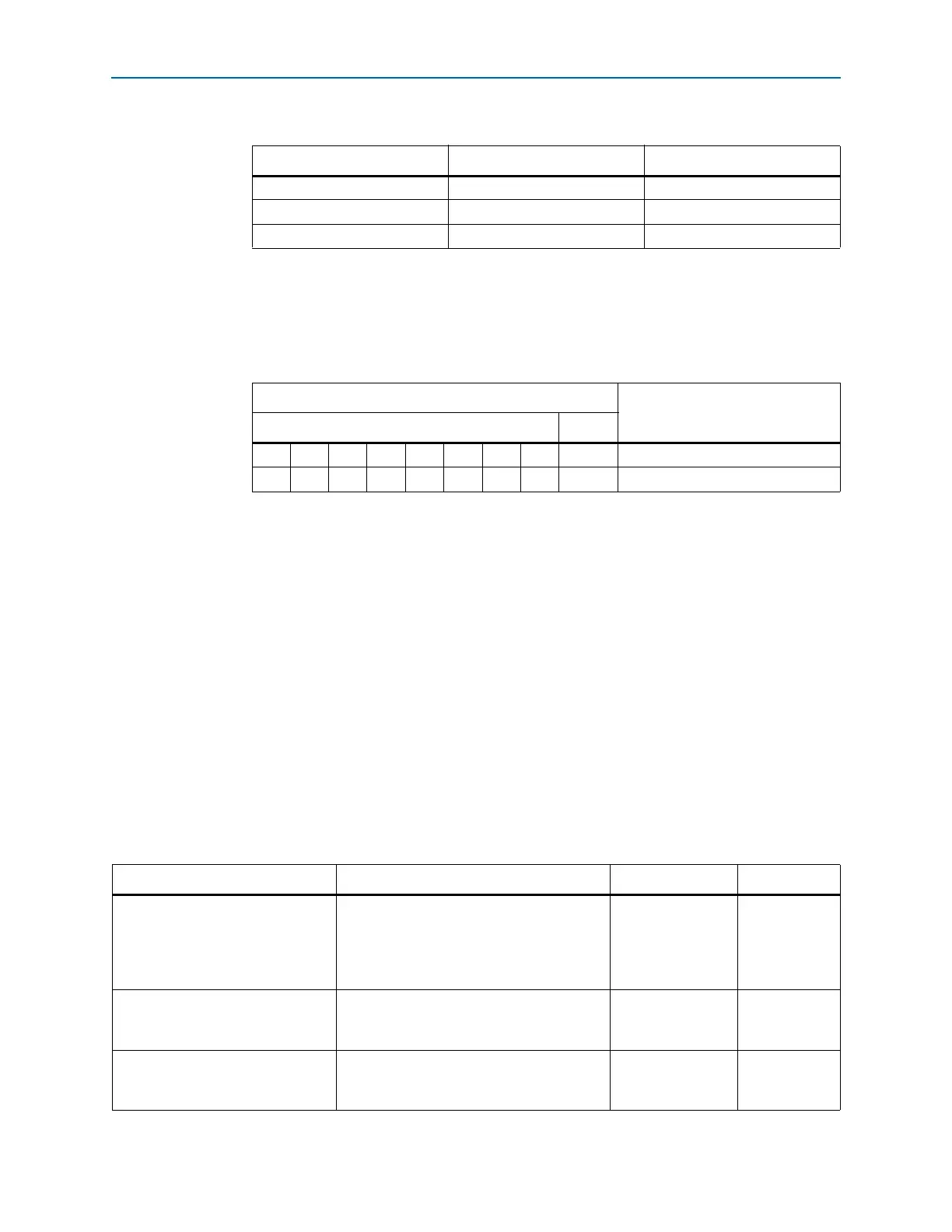
Bypassing a PLL Counter
Bypassing a PLL counter results in a divide (N, C0 to C4 counters) factor of one.
Tab le 5 –11 lists the settings for bypassing the counters in PLLs of Cyclone IV devices.
To bypass any of the PLL counters, set the bypass bit to 1. The values on the other bits
are then ignored.
Dynamic Phase Shifting
The dynamic phase shifting feature allows the output phase of individual PLL
outputs to be dynamically adjusted relative to each other and the reference clock
without sending serial data through the scan chain of the corresponding PLL. This
feature simplifies the interface and allows you to quickly adjust t
CO
delays by
changing output clock phase shift in real time. This is achieved by incrementing or
decrementing the VCO phase-tap selection to a given C counter or to the M counter.
The phase is shifted by 1/8 the VCO frequency at a time. The output clocks are active
during this phase reconfiguration process.
Tab le 5 –1 2 lists the control signals that are used for dynamic phase shifting.
Table 5–10. Loop Filter Control of High Frequency Capacitor
LFC[1] LFC[0] Setting (Decimal)
000
011
113
Table 5–11. PLL Counter Settings
PLL Scan Chain Bits [0..8] Settings
Description
LSB MSB
X X X X X X X X 1
(1)
PLL counter bypassed
X X X X X X X X 0
(1)
PLL counter not bypassed
Note to Table 5–11:
(1) Bypass bit.
Table 5–12. Dynamic Phase Shifting Control Signals (Part 1 of 2)
Signal Name Description Source Destination
phasecounterselect[2..0]
Counter Select. Three bits decoded to select
either the M or one of the C counters for
phase adjustment. One address map to
select all C counters. This signal is registered
in the PLL on the rising edge of
scanclk
.
Logic array or I/O
pins
PLL
reconfiguration
circuit
phaseupdown
Selects dynamic phase shift direction; 1= UP,
0 = DOWN. Signal is registered in the PLL on
the rising edge of
scanclk
.
Logic array or I/O
pins
PLL
reconfiguration
circuit
phasestep
Logic high enables dynamic phase shifting.
Logic array or I/O
pins
PLL
reconfiguration
circuit