Chapter 5: Clock Networks and PLLs in Cyclone IV Devices 5–37
PLL Reconfiguration
October 2012 Altera Corporation Cyclone IV Device Handbook,
Volume 1
■ Low time count = 1 cycle
■
rselodd
= 1 effectively equals:
■ High time count = 1.5 cycles
■ Low time count = 1.5 cycles
■ Duty cycle = (1.5/3)% high time count and (1.5/3)% low time count
Scan Chain Description
Cyclone IV PLLs have a 144-bit scan chain.
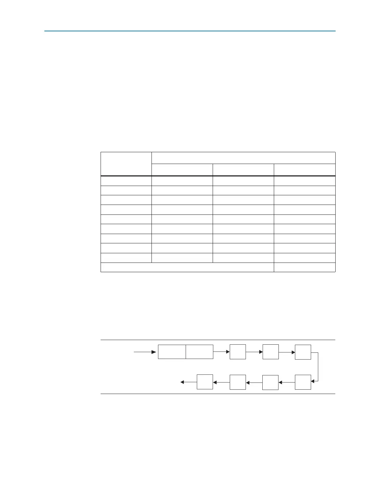
Tab le 5 –7 lists the number of bits for each component of the PLL.
Figure 5–24 shows the scan chain order of the PLL components.
Table 5–7. Cyclone IV PLL Reprogramming Bits
Block Name
Number of Bits
Counter Other Total
C4
(1)
16 2
(2)
18
C3 16 2
(2)
18
C2 16 2
(2)
18
C1 16 2
(2)
18
C0 16 2
(2)
18
M162
(2)
18
N162
(2)
18
Charge Pump 9 0 9
Loop Filter
(3)
909
Total number of bits: 144
Notes to Table 5–7:
(1) LSB bit for C4 low-count value is the first bit shifted into the scan chain.
(2) These two control bits include
rbypass
, for bypassing the counter, and
rselodd
, to select the output clock duty
cycle.
(3) MSB bit for loop filter is the last bit shifted into the scan chain.
Figure 5–24. PLL Component Scan Chain Order
DATAIN
C1C2C3C4
DATAO UT
MSB
LF CP
LSB
N MC0