2–20 Chapter 2: Cyclone IV Reset Control and Power Down
Dynamic Reconfiguration Reset Sequences
Cyclone IV Device Handbook, September 2014 Altera Corporation
Volume 2
2. After the PLL is reset, wait for the
pll_locked
signal to go high (marker 4)
indicating that the PLL is locked to the input reference clock. After the assertion of
the
pll_locked
signal, deassert the
tx_digitalreset
signal (marker 5).
3. Wait at least five parallel clock cycles after the
pll_locked
signal is asserted to
deassert the
rx_analogreset
signal (marker 6).
4. When the
rx_freqlocked
signal goes high (marker 7), from that point onwards,
wait for at least t
LTD_Auto
time, then deassert the
rx_digitalreset
signal
(marker 8). At this point, the receiver is ready for data traffic.
Reset Sequence in Channel Reconfiguration Mode
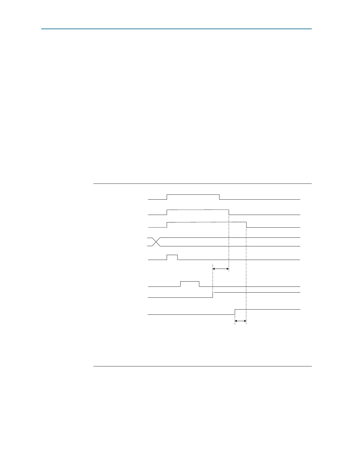
Use the example reset sequence shown in Figure 2–12 when you are using the
dynamic reconfiguration controller to change the PCS settings of the transceiver
channel. In this example, the dynamic reconfiguration is used to dynamically
reconfigure the transceiver channel configured in Basic ×1 mode with receiver CDR in
automatic lock mode.
Figure 2–12. Reset Sequence When Using the Dynamic Reconfiguration Controller to Change the
PCS Settings of the Transceiver Channel
Notes to Figure 2–12:
(1) For t
LTD_Auto
duration, refer to the Cyclone IV Device Datasheet chapter.
(2) The
busy
signal is asserted and deasserted only during initial power up when offset cancellation occurs. In
subsequent reset sequences, the
busy
signal is asserted and deasserted only if there is a read or write operation to
the ALTGX_RECONFIG megafunction.
Reset and Control Signals
4
Output Status Signals
7
8
busy (2)
2
Five parallel clock cycles
1
New value
3
6
1
1
1
5
tx_digitalreset
rx_analogreset
rx_digitalreset
reconfig_mode_sel[2..0]
write_all
channel_reconfig_done
rx_freqlocked
t
LT D _ Au t o
(1)