5–28 Chapter 5: Clock Networks and PLLs in Cyclone IV Devices
Hardware Features
Cyclone IV Device Handbook, October 2012 Altera Corporation
Volume 1
Clock Switchover
The clock switchover feature allows the PLL to switch between two reference input
clocks. Use this feature for clock redundancy or for a dual-clock domain application,
such as a system that turns on the redundant clock if the previous clock stops running.
Your design can automatically perform clock switchover when the clock is no longer
toggling, or based on the user control signal,
clkswitch
.
Automatic Clock Switchover
PLLs of Cyclone IV devices support a fully configurable clock switchover capability.
When the current reference clock is not present, the clock-sense block automatically
switches to the backup clock for PLL reference. The clock switchover circuit also sends
out three status signals—
clkbad0
,
clkbad1
, and
activeclock
—from the PLL to
implement a custom switchover circuit. You can select a clock source at the backup
clock by connecting it to the
inclk1
port of the PLL in your design.
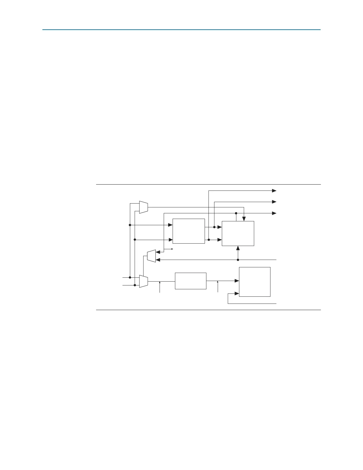
Figure 5–17 shows the block diagram of the switchover circuit built into the PLL.
There are two ways to use the clock switchover feature:
■ Use the switchover circuitry for switching from
inclk0
to
inclk1
running at the
same frequency. For example, in applications that require a redundant clock with
the same frequency as the reference clock, the switchover state machine generates
a signal that controls the multiplexer select input shown in Figure 5–17. In this
case,
inclk1
becomes the reference clock for the PLL. This automatic switchover
can switch back and forth between the
inclk0
and
inclk1
clocks any number of
times, when one of the two clocks fails and the other clock is available.
■ Use the
clkswitch
input for user- or system-controlled switch conditions. This is
possible for same-frequency switchover or to switch between inputs of different
frequencies. For example, if
inclk0
is 66 MHz and
inclk1
is 200 MHz, you must
control the switchover because the automatic clock-sense circuitry cannot monitor
primary and secondary clock frequencies with a frequency difference of more than
Figure 5–17. Automatic Clock Switchover Circuit
Switchover
State
Machine
Clock
Sense
n Counter
PFD
clkswitch
(provides manual
switchover support)
activeclock
clkbad1
clkbad0
muxout
inclk0
inclk1
refclk
fbclk
clksw