1–82 Chapter 1: Cyclone IV Transceivers Architecture
Self Test Modes
Cyclone IV Device Handbook, February 2015 Altera Corporation
Volume 2
BIST
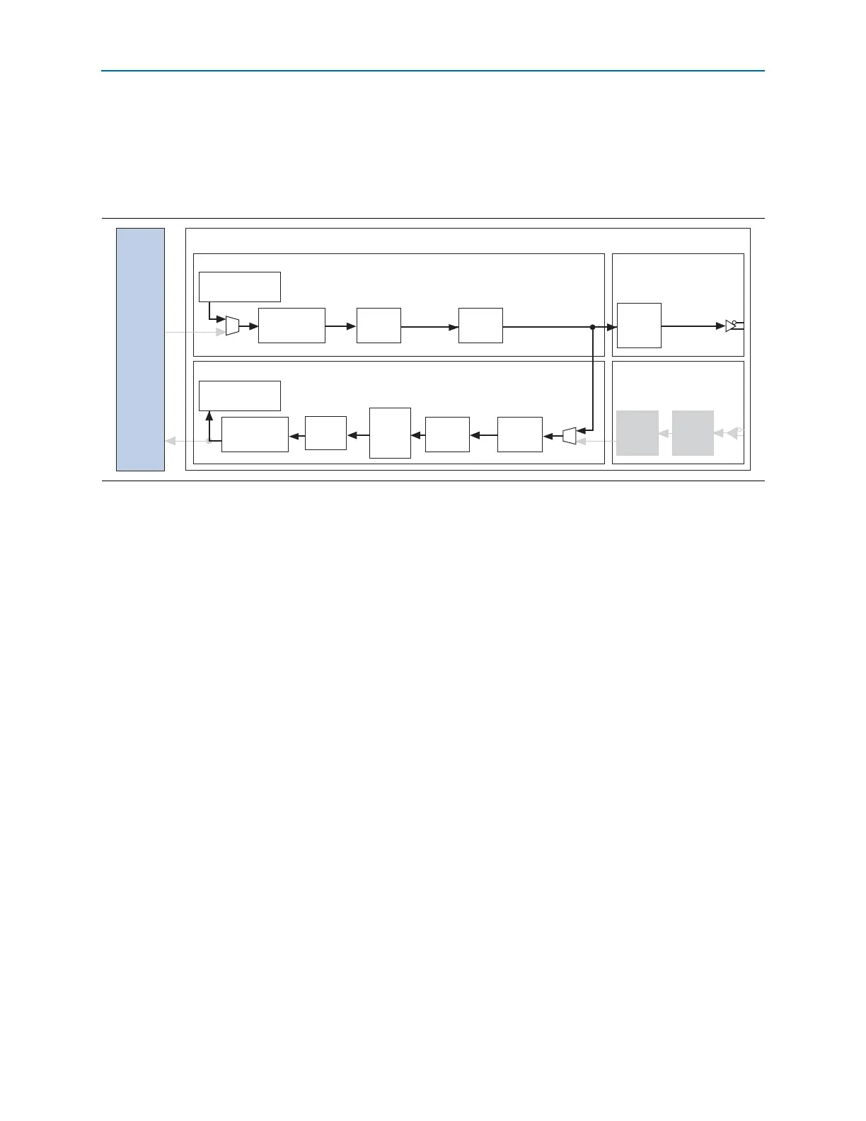
Figure 1–73 shows the datapath for BIST incremental data pattern test mode. The BIST
incremental data generator and verifier are located near the FPGA fabric in the PCS
block of the transceiver channel.
The incremental pattern generator and verifier are 16-bits wide. The generated pattern
increments from 00 to FF and passes through the TX PCS blocks, parallel looped back
to RX PCS blocks, and checked by the verifier. The pattern is also available as serial
data at the
tx_dataout
port. The differential output voltage of the transmitted serial
data on the
tx_dataout
port is based on the selected V
OD
settings. The incremental
data pattern is not available to the FPGA logic at the receiver for verification.
The following are the transceiver channel configuration settings in this mode:
■ PCS-FPGA fabric channel width: 16-bit
■ 8B/10B blocks: Enabled
■ Byte serializer/deserializer: Enabled
■ Word aligner: Automatic synchronization state machine mode
■ Byte ordering: Enabled
The
rx_bisterr
and
rx_bistdone
signals indicate the status of the verifier. The
rx_bisterr
signal is asserted and stays high when detecting an error in the data. The
rx_bistdone
signal is asserted and stays high when the verifier either receives a full
cycle of incremental pattern or it detects an error in the receiver data. You can reset the
incremental pattern generator and verifier by asserting the
tx_digitalreset
and
rx_digitalreset
ports, respectively.
Figure 1–73. BIST Incremental Pattern Test Mode Datapath
Transceiver
Receiver
CDR
Receiver Channel PMA
Serializer
Transmitter Channel PMA
Receiver Channel PCS
Transmitter Channel PCS
Tx Phase
Compensation
FIFO
BIST Incremental
Pattern Generator
8B/10B
Encoder
Byte
Serializer
Rx
Compensation
FIFO
BIST Incremental
Pattern Verifier
8B/10B
Decoder
Word
Aligner
Parallel
loopback
path
Byte
Deserial-
izer
Byte
Ordering
De-
serializer
FPGA
Fabric